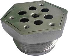
Stainless steel fittings and threaded accessories for immersion heaters
1. Immersion heater stainless steel fittings
 |
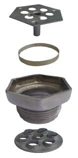 |
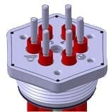
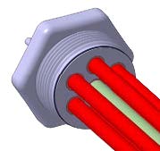
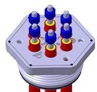
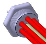
| Set for brazing | Set for TIG welding |
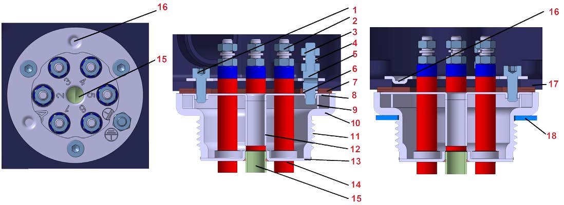
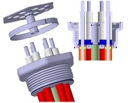
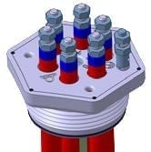
1.1 Brazing assembly description
 |
|||
| 1: Assembly screw, M4 2: Heating element terminals 3: Grounding nuts 4: Dented washer 5: Grounding stud M4 |
6: Dented washer 7: Silicone waterproof gasket 8: Hexagonal top plate 9: Brace 10: Fitting with machined sealing surface |
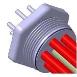
11: Thread with gasket groove 12: Pocket extension 13: Bottom plate 14: Heating element brazing 15: Pocket tube |
16: Rotation ring with centering bossings 17: Enclosure 18: Unlosable fitting gasket |
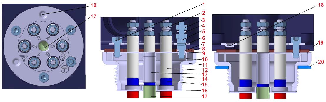
1.2 TIG welding assembly description
 |
|||
| 1: Assembly screw, M4 2: Heating elements terminals 3: Grounding nuts 4: Dented washer 5: Grounding stud M4 |
6: Rotation ring 7: Dented washer 8: Silicone waterproof gasket 9: Hexagonal top plate 10: Brace |
11: Fitting with machined sealing surface 12: Ceramic spacer 13: Pocket extension 14: Thread with gasket groove 15: Standard ceramic insulator |
16: Bottom plate 17: Pocket tube 18: Centering bossings 19: Enclosure 20: Unlosable fitting gasket |
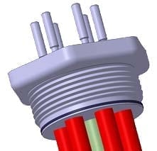
2. Immersion heater stainless steel fittings
Design:
– Fittings for incorporation by immersion heater manufacturers
– Designed to make 100% stainless steel immersion heaters, TIG welded, without brazed joints at a price similar to brazed brass fittings
– Exist in TIG version (unassembled) or brazed joint version (assembled)
– Fit the full range of immersion heater enclosures
– Compact size and short length result in reduced weight (Save + / -70% compared to plain stainless steel fittings)
– The fittings thread length allows throw wall mounting with fiber gasket and nut on wall of 6 mm thickness or on threaded socket with flat gasket
– Allows a 360° rotation of enclosure when mounted with their rotation ring
Range: BSPP1”1/2 and M45x2
– Threads rolled according to:
– ISO965-1 and 2 for metric threads
– ISO228-1 (Pipe threads without sealing in the thread) for thread called “Gas Thread”, also known as BSPP.
– Thread clearance for captive gasket
– Large chamfer facilitating correct assembly
– Large machined gasket seat
Manufacturing process:
Deep stamping, followed by threads rolling.
This technique allows a very limited machining, without material losses, and provides a good surface without porosity.
Assembly on enclosures:
– Through a hole in the enclosure. The enclosure is sandwiched between the fitting and a stamped inner ring. Bumps in the ring provide self-centering. This stamped ring costs only 10% of the conventional threaded inner rings.
Gasket between fitting and enclosure:
– The 3 mm thickness, ribbed, 50 Shore silicone gasket, absorbs flatness differences, and remains in place during tightening.
– Guaranteed IP65 ingress protection up to 200 ° C between fitting and enclosure, provided it has a flat bottom without asperities.
Grounding (earthing):
The grounding terminal does not impinge on the surface used for the heating element brazing, allowing the larger diameter heating element tubes and larger bending radius, and room for a center pocket tube. See general design of the grounding hereunder.
Heating element terminal numbering:
Heating element terminal numbers are stamped on the hexagonal top bracket.
Fitting gasket:
Three models of captive gaskets can cover all applications
– Non-asbestos fiber gasket, thickness 2 mm
– NBR O-ring, dia. 4 mm
– Flat PTFE gasket, thickness 2 mm
Inner stamped ring:
– The outside diameter less than or equal to the threaded rings allows to replace them without footprint problem.
– Its large inner diameter does not reduce the passage for heating elements
– The clamping with 3 BTR screws at 120° ensures a good pressure distribution and an excellent mechanical strength. These screw positions increase the clearances between the screw heads and live parts of the heating elements (If respecting the most favorable angle when drilling heating elements holes)
– The M4 recessed hexagonal hole screw heads allow easy and stable entry of hex wrench when adjusting angular position
– Ring made of stainless steel for better durability
– Unalterable stamped earthing logo
Fitting clamping: 9 mm wide hex part, 54 mm on flat for easy passage of wrench
Pressure resistance: 2 MPa (Fitting undrilled and without heating elements). Minimum wall thickness 1.2 mm
Fitting material:
Aisi 304L or Aisi316L stainless steel
Options:
– Special position or diameter of holes for heaters according to customer drawing (MOQ apply)
– Customizing or customer references marking (MOQ apply)
2.1 Stainless steel raw material
| Designation | Nearest equivalences | Specific gravity (g/cm3) | HRB hardness | Tensile
Strength, Stress, N/mm2 |
Elongation, % |
| Aisi 304L | SUS304L (JIL) X2CrNi1811 1.4306 (DIN) Z3CN18-10 (NF) 02Cr18Ni11 (GB) S30403 (ASTM) |
7.93 | <92 | >485 | >40 |
| Aisi 316L | SUS316L (JIL) X2CrNiMo17132 1.4404 (DIN) Z3CND17-12-02 (NF) 02Cr17Ni12Mo2 (GB) S31603 (ASTM) |
7.98 | <95 | >485 | >40 |
Composition
| C | Si | Mn | P | S | Ni | Cr | Mo | |
| SUS 304L | ≤ 0.03% | ≤1.00% | ≤2% | ≤0.045% | ≤0.030% | 9.00-13.00% | 18.00-20.00% | – |
| SUS 316L | ≤ 0.03% | ≤1.00% | ≤2% | ≤0.045% | ≤0.030% | 16.00-18.00% | 12.00-15.00% | 2.00-3.00% |
2.2 Stainless steel Rohs compliance
According to the Directive 2011/65/ dated June 8, 2011 (Rohs), stainless steel alloys are allowed to have a maximum of 0.1% by weight of lead, lead, mercury, hexavalent chromium, PBB (Polybrominated biphenyls), PBDE (Polybrominated Diphenyl Ethers) and 0.01% of Cadmium in weight.
(Provisions of Article 4 and paragraph 1 of Annex II)
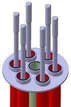
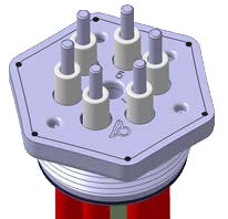
3. Assembly process of stainless steel fittings on heating elements (TIG welding)
| 1 Make heating elements with extended terminals |
2 TIG butt weld heating elements on the washer. Pocket must be welded first. (Welding lines are figured in black) |
3 Fill with resin, and put usual ceramic insulators |
4 Proceed to TIG weld of washer on fitting frame (Att.: for correct welding position, tentatively put hexagonal plate and ceramic spacers ) |
 |
 |
 |
 |
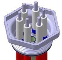
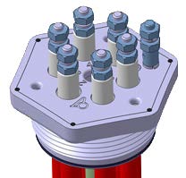
| 5 Assemble ceramic spacers |
6 Assemble hexagonal plate and spacer ring on heating element outputs |
7 TIG weld of hexagonal plate at the same level than the fitting frame edge |
8 Fit terminals with nuts and washers and screw the grounding terminal |
 |
 |
 |
 |
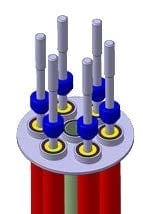
4. Assembly process of stainless steel fittings on heating elements (Brazed)
|
1 |
2 Insert heating element tubes in the bottom plate holes, until they protrudes from hexagonal plate of the insulation distance requested by standards |
3 Proceed to brazing of heating elements on the bottom (Brazing lines shown in brown) |
 |
  |
 |
| 4 Fill with resin or elastomere and put usual ceramic insulators |
5 Clean the brazing areas |
6 Fit terminals with nuts and washers and screw the grounding terminal |
 |
 |
 |