Historical introduction of ceramics used in connection blocks
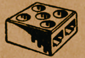
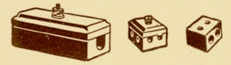
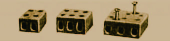
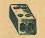
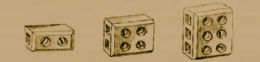
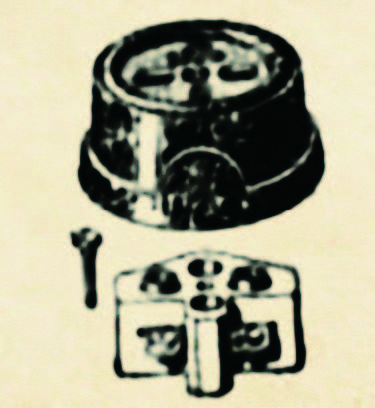
 Porcelain connection blocks, 1930-1950s (Ultimheat collection)[/caption]
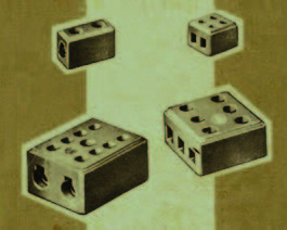
Porcelain
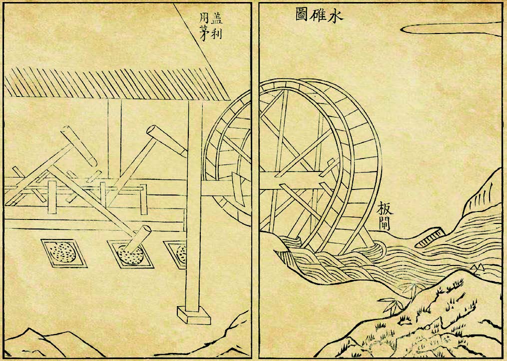
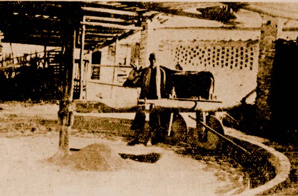
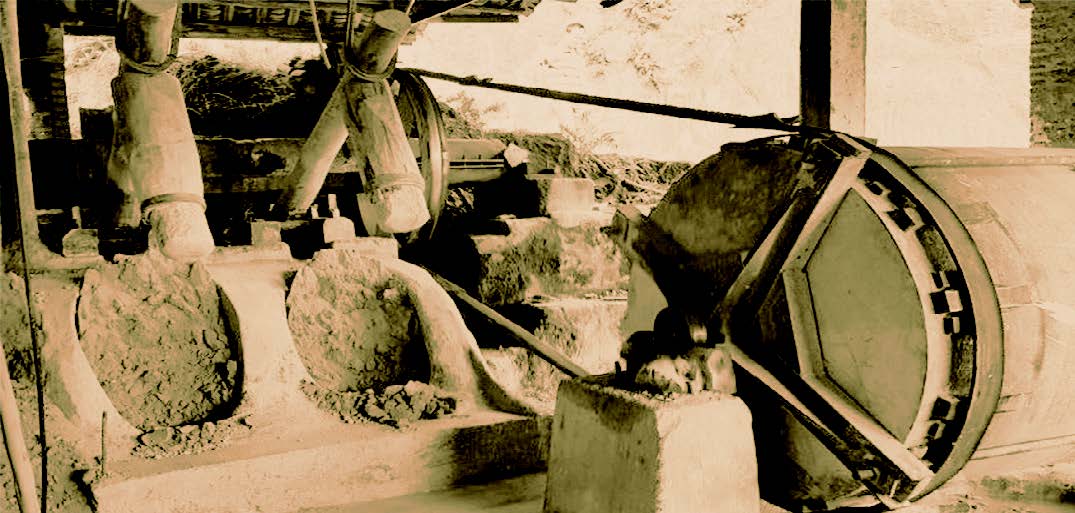
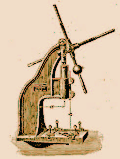
Hard Porcelain, originated from China, whose manufacturing process has been closely guarded for centuries, owes its characteristics of whiteness, fineness, resistance to temperature, and hardness to the use of two particular minerals, kaolin, (“Gao Ling Tu 高 岭 土 ” in Chinese, which can be translated as “Clay of Gao Ling City”, located north-east of Jingdezhen in Jiang Xi Province), and “Pu Tong Ci 普 通 瓷 ” (translation: common ceramic). Kaolin is quite friable, and Putongci is a hard stone. Extracted into blocks, they are then broken into gravel by waterwheel and trip-hammer with a hard stone head, then reduced to a fine powder by rolling and falling stone balls into rotating wooden barrels or grinding wheels. These two machines were most often operated by a waterfall on a paddle wheel.
The powders are then decanted in cascading water tanks, where they lose their impurities that are deposited by decreasing particle size. The finest powders are used to make enamel. Pasta, mixtures of different grain sizes, are then kneaded and put to rest in blocks called balloons. This is the stage of “rot” that lasts for several days, during which a chemical transformation of the dough takes place. According to Marco Polo, the Chinese porcelain manufacturers let the decay act for several generations …
 |
 |
 |
 |
 |
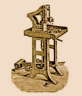
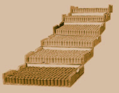
| Traditional production machines (( 水碓 shui dui) for production of powders used to make electric porcelain (private collection) | Traditional Chinese Dragon oven ( 龙窑 Long Yao), feeding mouth and filling method with electric porcelains (private collection) | |
In Europe, the secret of the manufacture of hard porcelain was first discovered by the chemist Boeticher at the court of Saxony, in the last years of the 17th century, by mixing different ores to make heat resistant crucibles. Its manufacture was immediately transferred to Meissen on the Elbe, near Dresden. Secret of state, manufacture of this porcelain, known since “Porcelain of Saxony” was particularly controlled.
Then, in two letters dated 1712 and 1722, the Jesuit missionary François Xavier d’Entrecolles described (with some inaccuracies) the manufacture of porcelain as he had discovered in China.
When he talks about kaolin, this ore is unknown in France. This white clay ore may contain up to 80% kaolinite of the molecular formula Al2Si2O5(OH)4, which is the active ingredient. It is especially its high concentration of alumina that gives it its high melting temperature, whiteness and hardness. But pure kaolin is almost infusible, and is not the only ingredient, and European scientists, after importing it, failed to make porcelain because they did not understand the importance of the second one. They lacked the “Putongci” this hard stone made of quartz and feldspar.
In 1727 and 1729 M. de Réaumur, in two memoirs read at the Sciences Academy in Paris, put forward the idea that the infusible Kaolin could only be one of the components and that the second ingredient, the Putongci, would help to melt by serving as a binder and lowered the melting temperature. On this basis, he succeeded in producing porcelain. Since these two materials did not have known equivalents in France at the time, things remained the same. Nearly 40 years later, in 1766, the Comte de Lauragais presented hard porcelain at the Academy, without wishing to give the composition.
In 1767 was accidentally discovered, by doctor Darcet’s wife, the kaolin field at Saint Yrieix la Perche near Limoges. In 1768 after an examination of the material done by the Academy of Sciences, and tests made in 1769, the first productions was started in Limoges in 1771. This was the origin of the porcelain industry in Limousin.
Then Nicholas Christiern De Thy of Milly brought back from Dresden, where he had been able to visit various factories, the exact process of manufacture. He gave the description at the Royal Academy of Sciences on February 13, 1771. From this, he made a book “The Art of Porcelain” in 1777. Since then, hard porcelain began to be manufactured in France. It was reserved, by royal privilege exclusive to the Manufacture de Sèvres.
The revolution of 1789 put an end to this privilege, but porcelain remained confined to crockery and luxury decorative objects.
Little developed in France until 1840, the manufacture of porcelain was not really industrialized until the 1880s with the first steam engines and coal firing instead of wood.
The first uses in electrical circuits:
The arrival of telegraph and porcelain insulators
In 1729, Stephen Gray had defined the concept of conductors and insulators. At that time, electrostatic machines and laboratory apparatus required electrical insulators. First, glass was widely used. The first batteries also used glass as a container, but also as an insulator.
The arrival of the telegraph in the years 1855–1860 was at the origin of enamelled hard porcelain insulators used on poles for holding telegraph wires. It turned out then that those in porcelain were more insulating than those in glass. In England, ivory insulators were tried and found excellent for this purpose. Fortunately, they were not generalized any more than the bone insulators that were also considered.
As early as 1860, telegraph lines used tens of thousands of porcelain insulators. Two years later, it was hundreds of thousands. Electric porcelain is then subjected to numerous tests, each producer having his recipe, often related to the composition of the existing ores nearby. Generally, it is a mixture of kaolin, clay, quartz and feldspar, baked around 1400°C. It is kaolin and clay that give its plasticity, while quartz is a degreasing element. The feldspar, whose melting point is much lower than those of the other constituents, ensures the vitrification of the mixture. The contents are substantially 50 percent kaolin, 25 percent feldspar, 25 percent quartz. Excellent electrical insulator, it is most of time waterproof, acid-proof and can withstand great temperature change without cracking. Its enamel provides a smooth and non-porous surface.
At the Universal Exhibition of 1878, two Paris producers of porcelain insulators are already exhibiting.
Three years later, at the International Electricity Exhibition in 1881 in Paris, there are already a dozen producers of insulating porcelain pieces, for telegraphy but also for electrical networks and circuits that are beginning to appear. In 1888 porcelain insulators are universally used on utility poles for street lighting. At the end of the 19th century, its use became progressively common in most domestic electrical appliances: lamp-holders for light bulbs, switch boxes and sockets, plugs, bases and supports of heating resistors, junction boxes, fuse holder, etc.
In 1892 was founded in Paris, rue des Arquebusiers, the Pertus company which began to produce porcelain parts for electricity. (This company closed in 2004)
At the World Exhibition of 1900, electric ceramics were present in many forms: insulating pieces, but also insulating enamels (Godin to Guise), sintered heating rods comprising conductive powders, porcelain insulating pieces (Parvillée Frères).
It should be noted that the pioneering work of the brothers Achille and Louis Parvillée in resistive ceramics was widely commented as early as 1900 in international technical journals in Germany and the USA. The technology of the high-temperature sintered powders they developed in Paris, 26 Gauthey street and after 1898, in their new factory in Cramoisy (Oise), gave rise to very high-temperature silicon carbide heating resistances, such as Silite, around 1913, Globar, around 1926.
 |
 |
 |
The arrival of electrical insulated porcelain terminal blocks
In 1905, the increasing number of electrical applications of porcelain made competition very important, and the price fell sharply. Competition with German and Austrian producers was fierce.
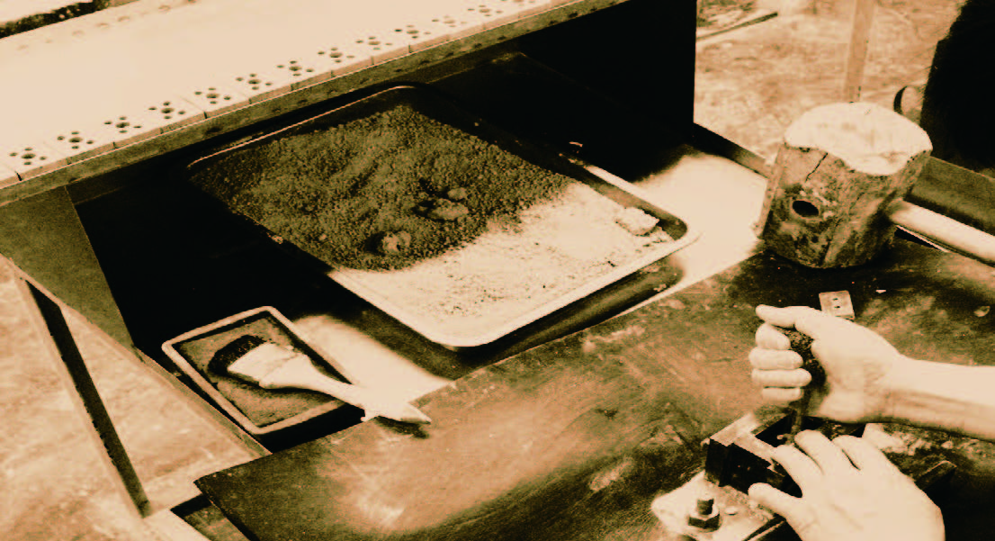
In Germany, the manufacture of small electrical insulating porcelain was done with moistened powders compressed by manual shock or pedal presses. In France, this process was virtually unknown. A similar technique existed for faience, but its transposition to the manufacture of electric porcelain had not yet been developed. The process consisted in producing a granulate moistened with a mixture of oil and water: 0.2 to 0.3 parts of vegetable oil, 1.0 to 1.5 parts of petroleum oil and 2 to 3 parts of oil. water. To 100 parts of paste were added 12 to 17 parts of this mixture. (Later this mixture will be replaced by diesel oil). The wet powder was then passed by hand through a sieve; The quantity of powder required was placed in molds, where it was compacted by shock presses. In a more artisanal version, the pieces were pressed by closing the mold and striking it with a hammer. Demoulded, the terminal block was then left to dry for several days before being covered with a layer of enamel and fired. This method gave many rejects: due to the inhomogeneity of the powders, the irregularity of the quantity placed in the mold and the irregularity of the pressures exerted produced cracks, and the porcelain was porous. For these reasons, electricians at the time considered that porcelain was a bad insulator and that only the enamel layer was insulating. In 1902–1905 The insulating characteristics of electric porcelain were not absolutely analyzed and understood. (Research by M.S. Watts in Transactions of the American Ceramic Society, IV, 1902, 86; La Ceramique, 1903, pp. 3 and 19; Sprechsaal, 1903, pp. 519 and 557).
 |
 |
 |
 |
 |
 |
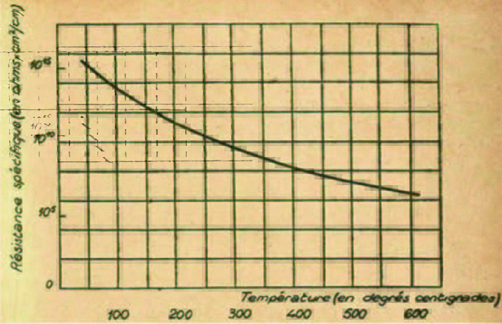
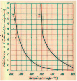
In 1911 was printed a book often referenced on the manufacture of porcelain insulating pieces: « Les substances isolantes et les méthodes d’isolement utilisées dans l’industrie électrique, by Jean Escard ». If the author specifies the average compositions of electrical porcelains, his data on the variation of the electrical resistivity as a function of the temperature are fragmentary and limited, and also show that in the minds of the builders, the glazing is more important than the composition of the porcelain. It dedicates only 3 lines to the uses of porcelain in switch bases, lampholders and other small components. In 1919, in Paris, at the instigation of the “Comptoir des fabricants de produits réfractaires”, a ceramic testing laboratory was created.
The same year, a decorative porcelain manufacturer from Limoges, Frédéric Legrand joined forces with Jean Mondot, director of the Mondot Company, Vinatier and Jacquetty, who had manufactured in Exideuil in Dordogne, since 1905, porcelain electrical switches for household lighting. From this association will be started the electrical division of Legrand.
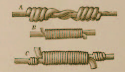
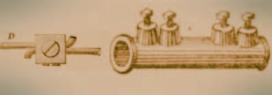
The years 1920-1930, following the development of electrification, will see a huge development of the electrical components industry and many other manufacturers will put porcelain terminal blocks to their catalog : Moor, Fournet, Bouchery, Samet, Pétrier, Thomson etc. Porcelain terminal blocks, of small dimensions, sometimes without fixing holes are then mainly used in the domestic wiring of the lighting networks, replacing splices covered with chatterton. Some will have 2 set screws for each driver.
In December 1923 was inaugurated, in Ivry-Port near Paris, a laboratory intended for the test of the insulating ceramics able to produce electric discharges reaching a million volts. (The Journal, December 12, 1923)
 |
 |
 |
 |
 |
 |
 |
 |
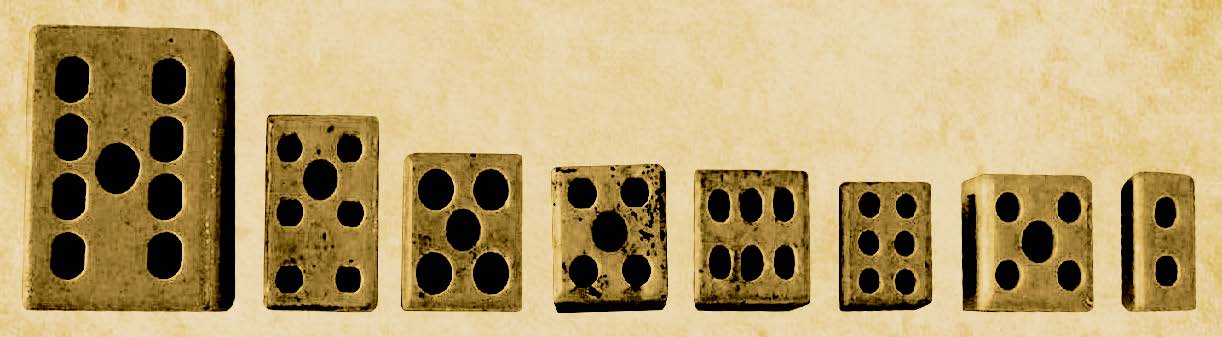
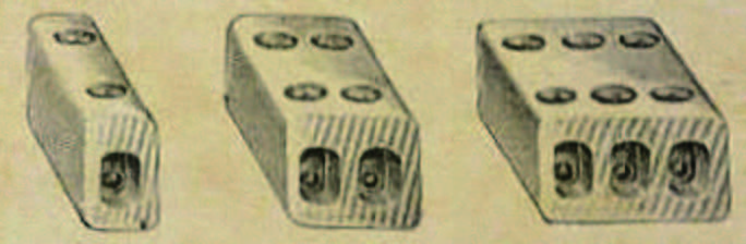
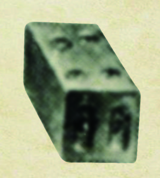
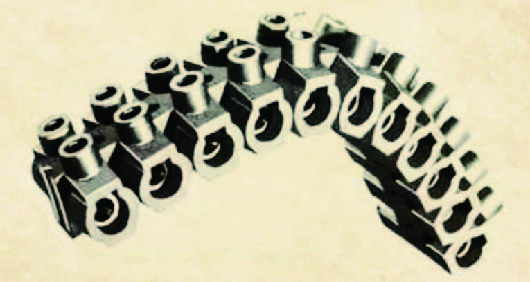
Because of their resemblance, especially for those of the two-wire range of Legrand, porcelain terminal blocks were called “dominoes” by the electricians. Because of their shape and whiteness, they were also called “sugar cubes”.
They were widely used in the connections of electric stoves and ovens which developed strongly in the 1930s. The fixing hole appeared then, to allow the assembly of the terminal blocks on the sheet metal work. But this new application, especially in electric stoves ovens, showed limits to their temperature resistance: at 150°C the porcelain gradually loses its dielectric properties as temperature increases. Above 300 ° C, it undergoes chemical transformations that make it a bad insulator, especially for electric porcelain with a low percentage of kaolin.
Evolution of diameters and cross-sections of electrical conductors
 |
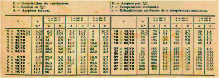 |
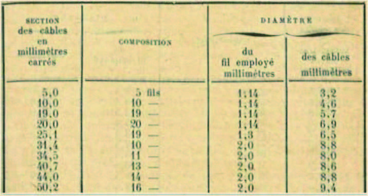
In the early days of the manufacture of copper electrical cables, preference was given to limiting wire diameter ranges, and the section in mm² of the cables was only the consequence of wires diameters and not the basis of the cable sections. In 1910, a series of sections of conductors was proposed identical to that of the current standards: 0.75mm²; 1; 1.5; 2.5; 4; 6; 10, 16; 25; 35; 50mm². (Aide-mémoire de poche de l’électricien par Ph. Picard, et A. David)
But this attempt at standardization did not last, it was the cable manufacturers who, according to their manufacturing requirements, fixed the cross-sections. In the Bouchery catalog of 1933, answering the specifications established by issue 137 of the “Union des Syndicats de l’Electricité”, it is no longer the section which serves as a reference in the series, but the diameter of the conductors, established in 10th of a mm: 7/10; 9/10; 12: 10; 16: 10.20 / 10; 25/10; 30/10; 34/10 etc.
In 1954, a beginning of normalization according to the section in mm² appears for the wired conductors: 5.5mm²; 8mm²; 10mm²; 14mm²; 18mm²; 22mm²; 30mm²; 40mm²; 50mm² etc., but the rigid conductors are always given in 10th of a mm: 12/10; 16/1; 20/10, 25/10; 31.5 / 10.
In 1963, Legrand still gives the following relationships for its porcelain terminal blocks:
Dia 2.5 for 3mm² conductor Dia 3.5 for 5.5mm² conductor Dia 4.5 for 10mm² conductor Dia 5.5 for 18mm² conductor Dia 8.5 for 40mm² conductor Dia 9.5 for 50mm² conductor
In 1983 the sections of the wires were standardized, the 3mm² became 2.5mm², the 5.5mm² became 6mm², the 18mm² became 16mm², the 40mm² became 35mm². The 4mm² and the 25mm² were created.
Currently it is the IEC 60228 standard that defines the standard sizes of conductors in electrical cables.
Steatite
Steatite was known by many names,
- Under the name of ollare stone or potstone, (from the Latin “ollarius”: used to make pots), because the fineness of its grain, its little hardness, its inalterability to fire allowed to turn around the pots and cauldrons . This feature is still known by current artists who use it because it is soft and easy to carve.
- Under the name of talc, for its touch soft powder version
- Under the name of steatite, to describe its fire-hardened version. In this form, Johann Heinrich Pott (1) describes that before 1700 the inhabitants of the mountain Fichtelberg harden this stone by firing to put it in a state of being polished to make small balls, buttons and send loaded full carts in Nuremberg,
(1) ” Lithogéognosie, ou Examen chymique des pierres et des terres en général et du talc, de la topaze et de la stéatite en particulier”. French edition of 1753.
At the beginning of the 19th century, it was used for the manufacture of cameos and other decorative objects.
But it was the industrialists of the Nuremberg region who used the peculiarity of this mineral as early as 1854–1855, to give after cooking a hard and heat- resistant ceramic for a new application: the gas burners. The main suppliers were Johan Von Schwarz and Jean Stadelmann from Nuremberg, both of which were the main owners of the only known steatite mines known at that time. They were grouped in a union called “Gas Burners” including the 6 producers of Nuremberg plus Lauboeck and Hitpert de Wunsiedel in Bavaria.
As early as January 1856, Johan Von Schwarz had filed a patent in France on the ways of hardening soapstone and alumina silicates. For 40 years, steatite did not find other industrial opportunities.
Around 1894, acetylene lighting began to develop, which had the inconvenient to produce a very hot flame that destroyed the burner nozzles. At the Universal Exhibition in 1900, a Parisian engineer, Louis M. Bullier, won a gold medal for his steatite gas acetylene gas nozzle patented in March 1895. (Louis Bullier, Henri Moissan’s collaborator, had participated in the production first electric furnaces for the manufacture of calcium carbide and invented, besides an industrial method for the production of calcium carbide, the first functional burner nozzles for acetylene lighting)
Little known, except for this application, steatite is mentioned only for memory in 1905 in the course of the professor A. Granger on industrial ceramics. Its recent applications in electrothermal and lighting were still too limited and recent.
Shortly after, around 1907, the “Société Française d’Articles en Stéatite”, 10 place des Vosges, also began manufacturing steatite parts for electrothermal applications.
The need for automotive sparkplug insulators and high-temperature insulators for electric heating provided new opportunities.
To introduce himself in this new booming market, in 1908, the domestic porcelain manufacturer Philipp Rosenthal & Co. AG acquired the Thomaswerke factory in Marktredwitz, opening its activity to electro-technical porcelain.
In 1911 Jean Escard (*) considers soapstone as a good insulator, which has only been used for a short time in electric insulating plates and spark plugs, than in its native form, easy-to-machine soapstone. but with limited mechanical strength, inferior to porcelain and marble. Its use in high-temperature baked form like porcelain is apparently not known to him. (*: Insulating substances and insulation methods used in the electrical industry)
Thanks to its technical advance and the quality of the soapstone from their mines, the German Nuremberg Trade Union maintained a near-global monopoly and controlled prices on the production of steatite parts, burner nozzles, car sparkplugs insulators and heating resistances insulators until 1914.
The blockade of the First World War intensified the search for ore outside Germany and ended the monopoly, but the lobby of the German producers remained intact and comforted Germany’s advance in the electro-technical ceramics industry.
In 1921 Rosenthal began to cooperate with the manufacturer AEG for the manufacture of technical porcelain, and in 1936, the two joined to create Rosenthal Isolatoren GmbH which became one of the major actors of the sector.
 |
 |
 |
 |
On 21 November 1916, since the blockade deprived France of the German steatite needed for cars sparkplugs, they became a critical military component. The industrialist Jules-Edouard Delaunay, 88, boulevard du Port-Royal, and the chemist Georges-Louis Dimitri, 7, rue Victor Considérant, then took in France, the patent n ° 505.386 for the manufacture of compressed steatite. This patent was completed by a second, No. 498.015, dated July 16, 1918. This material was quickly recognized as the perfect insulator for car sparkplugs, but also for the heaters and burner nozzles for gas lighting. It consisted mainly of 61.8% silica, 28.1% magnesia and 5.1% alumina. It combines hardness, electrical insulation at high temperatures and high frequencies, and resistance to high temperatures.
In 1919 was founded a competing company “Industrial Steatite, Ets E. Robert and Co.” in Montreuil-sous-Bois, which specialized in the manufacture by compression of insulating parts for electrothermal equipment.
Jules-Edouard Delaunay and Georges-Louis Dimitri applied for the mark Isolantite on August 3, 1920, and thanks to the close relations taken during the war with an American industrialist, Major De Caplane, was also set up the company Isolantite USA, which then in a few years became the largest American specialist in ceramic insulation in the booming radio industry.
In 1927, on October 18th, in the wake of the success of the Isolantite, was created the S.A. L’Isolantite, at 52, boulevard Garibaldi in Paris.
In the years 1925–1930, the German industry of steatite and industrial porcelain, was in the hands of a main group: the “Steatit-Magnesia AG” (Stemag AG) founded in 1921 in Hollenbrunn near Lauf on Pegnitz in Bavaria, a traditional center of ceramics and steatite. This company, developing in Europe, took control in 1928 in England of Steatite and Porcelain Products Ltd. in Stourport-on-Severn, Worcestershire.
In France, this group created the Steatit-Magnesia factory at 206 rue Lafayette in Paris. In 1970 the group joined AEG, then in 1971 with Rosenthal to become Rosenthal Stemag Technische Keramik GmbH.
In Europe and USA, many types of electrotechnical ceramics with various characteristics were developed in the years 1930–1940, among which we can mention: Sinterkorund, Isomar, Pyranite, Pyrodur, Calite, Calan, Frequenta, Ardostan , Sipa, Condensa, Kérafar, Rheostite, Calodure, Aloska, Morganite, Globar Each manufacturer of technical ceramics giving a name to a type of product. The French company L. Desmarquest et Cie, specialized since the beginning of the 19th century in ceramic crucibles with a high percentage of alumina, began manufacturing insulators for heating resistances under the brand name Ohmolithe.
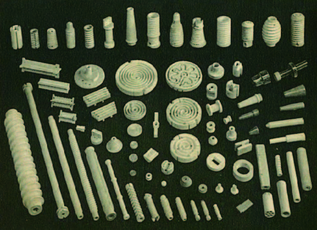
Immediately after the Second World War, when due to lack of fuel, heating and especially cooking gave preference to electricity, steatite will become the preferred electrical insulation for high temperatures. Thermally and mechanically resistant, (vibration and shock), retaining good insulating properties at high temperature (up to 600°C) it will be and will remain used in a large range of electrical industries inside spark plugs, switchgears, heating elements, railway radiators, liquid heaters, heating switches, insulating beads, hotplate connector bases etc …
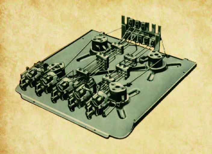
It was naturally chosen for the manufacturing of terminal blocks to withstand temperatures above 250-300°C. In this 1949 catalogue of Arthur Martin electric stoves, one can see the use of dozens of steatite parts.
In certain applications where dust caused by the condensation of moisture may appear, it was sometimes glazed.
Depending on the type of atmosphere of the firing oven used, it can be white (reducing atmosphere) or yellow (oxidizing atmosphere).
 |
 |
Automation of the die casting of ceramics
In 1930, Isolantite USA began to automate the compression molding of steatite by modifying pressing machines for pharmaceutical tablets (James Millen, August, 1937 issue of QST magazine p.65).
In the early 1960s, a new technique of injection molding of steatites, and in general ceramics, called low pressure injection, was invented in Russia by P.O. Brobosky. (P. O. Gribovsky: ‘Hot casting of ceramic products’, 1961, Moscow Leningrad, GosEnergoIzdat)
Injection molding technology relies on the ability of ceramic mixtures, prepared with a specific polymer binder and heated to a certain temperature to have the consistency of modeling clay, and to flow under pressure, into metal molds. When the part is cooled in the mold, it solidifies, and can then be demolded and fired. The binder is then vaporized during firing. In the 1970s two main methods of injection molding were developed. Their main difference is the type of temporary binder and the associated pressure applied. Because of these differences, there is a distinction between equipment used for shaping ceramic components and the process for removing binders. The first method, called high-pressure injection molding, relies on the use of thermoplastic organic compounds, which become fluid at temperatures of 150 to 300°C (polypropylene, polystyrene). In this case, a ceramic powder is plasticized with this binder in the temperature range where it is melted, cooled and cut into pellets. These granules are then heated and introduced into the injection machine. The shaping is carried out under fairly high pressures (5-70 MPa) in metal molds. After demolding, the part obtained is subjected to combustion of the binder during a subsequent firing.
Another method, called low-pressure injection molding, relies on the use of thermoplastic organic compounds, which become fluid at relatively low temperatures, of the order of 60-70°C. The main component of this binder system is paraffin wax, which melts at this low temperature. Because the paraffin- based ceramic polymer compositions have a rather low viscosity and good fluidity, very softness and plastic properties at rather low temperatures, these compositions require only low pressures (0,2-0,7 MPa). In this case, a ceramic powder is mixed and plasticized with this paraffin binder system at 60- 70 ° C and the prepared composition is injected into the metal molds. When the mold is cooled, the part is ejected. The paraffin is then vaporized at high temperature in an oven and then the ceramic is fired.
Manufacturers of special automatic machines for the production by molding of ceramic parts by low pressure injection were born in the 70s. The oldest seems to be in 1978 Peltsman Corporation in the USA. These methods revolutionized the manufacture of ceramic technical parts.
The arrival of thermoset plastics and thermoplastics.
The arrival of thermosets in the 1930s allowed the manufacture of many electrotechnical parts by thermocompression, but did not replace the ceramic in the terminal blocks. In its catalog of 1932, where it describes itself as “Only French house currently manufacturing a set of small equipment Bakelite” the Company Maure uses Bakelite only for lids and boxes, and keeps the ceramic for the bases and supports of terminals.
But Bakelite was a revolution in the small electrical apparatus, for all the structural elements.
“Over the last twenty years, the multiplication of materials used or usable in electrical engineering has been such that it has become difficult for an engineer to know all their particularities … with so-called plastic materials used as insulators or dielectrics we see the electrotechnical applications undergo profound changes “. (1945 Matériaux électrotechniques modernes, Ultimheat Museum)
The arrival of thermoplastics around 1955 allowed the invention of flexible nylon terminal blocks. But none of these materials allowed use at temperatures above 150 ° C.
 |
 |
 |
Rising of electrical standard
 |
 |
 |
 |
 |
 |
As early as 1887, the ” Journal du Gaz et de l’Electricité”, at the instigation of an insurance company, published the first known regulation on the safety instructions to be taken for the installation of electric lighting. This regulation specified that “the size of the wires must be proportioned to the current which must cross them so that the temperature does not exceed 80 degrees centigrade, … the junctions of the wires will have to be electrically and mechanically perfect”, but without specifying more.
The law of June 13th, 1906 on the distribution of energy added an imperative of additional security by specifying that the losses of current through the insulation could not exceed 1/10.000th of the current which circulated there. (For a 230V 10A circuit, this gives a value of the insulation resistance of 230 kΩ).
In 1907 was founded an electrotechnical standardization body: “l’Union des syndicats de l’électricité” (U.S.E.) at the initiative of the Professional Union of Electrical Industries and the Professional Union of Electricity Plants. This body gradually implemented a standardization of equipment, components, wires and cables.
In 1915, the inter-union brand UNIS-France was created, awarded to manufacturers guaranteeing the French origin of their products.
In 1922, was founded the ” Société pour le Développement des Applications de l’Électricité (AP-EL)”, by the Parisian Company of Distribution of Electricity and the sectors of the Paris area, which establishes a first quality mark then called “The Hand that marks” for household appliances. However, it did not apply to components or small equipment.
In 1925, the U.S.E quality mark was created by the Union of Electrical Equipment Manufacturers. It applied to small electrical equipment, including terminal blocks. It had been made necessary because of the increasing competition between the manufacturers, which was lowering the quality of the products. In 1927 it became the USE-APEL mark.
The first normative regulation for the components appeared in 1928 in the publication no. 67 of the USE: “Rules of establishment of the small electrical equipment for a maximum current of 25 amperes”. In the third part, a series of specifications for ceramic terminal blocks were defined: insulation, spacing of live parts, partitioning, terminal hole diameter, wire clamping, copper cross-section, electric contact surfaces.
Some terminal blocks began to bear this “USE” mark.
The devices were regulated at the same time by Publication No. 184: “General and Private Technical Regulations Established for the Granting of the USE-APEL Quality Mark to Appliances”.
Following the appearance of plastic materials, the USE published in 1935, a pamphlet No. 46, “Test methods for molded insulators”, which was modified and completed in 1941 by the “Methods of testing plastics”. used in electrical construction “. These tests defined methods and specimens whose current standards are directly derived.
The U.S.E. was renamed in 1938: U.T.S.E “Union Technique des Syndicats de l’Electricité”,
In 1939 appears the mark of quality NF, attributed by the Afnor, which will become effective only after the second world war. The APEL then adds to its logo the NF mark.
In 1947 the “”Union Technique des Syndicats de l’Electricité”” became the ” Union Technique de l’Electricité (UTE)”. The USE logo for the components was not changed.
In 1951, the dimensions of copper electrical conductors were standardized by standard NF C19, and the rules of construction of small apparatus by circular No. 67, domestic installations by the rule USE 11 and its circular No. 11.
In 1957, the standard NF C11 specified that in domestic installations, the junctions and derivations of the conductors will preferably be made using screw connection devices or equivalent, attempting in this way to terminate the splices covered with “Chatterton tape” which were widely practiced.
When they first appeared in the early 1970s, the international electrical safety standards for household electrical appliances (IEC 60730 and IEC 60335 series) clearly differentiated between ceramic and thermoplastic and thermosetting insulators, giving the best insulation characteristics to ceramics, including a CTI above 600, and many test exemptions. They also gave a maximum limit temperature for internal brass parts (210°C), nickel-plated brass (185°C), nickel-plated steel (400°C), and stainless steel (400°C). Their recent evolutions favored ceramics even more.
In 1990 appeared the most current standard for electrical terminal blocks: IEC (EN) 60998 and in particular part 2, “Connecting devices for low-voltage circuits for household and similar use – Part 2-1: special requirements for safety devices”. connection as separate parts with screw clamping devices “. This standard redefines in particular several critical parameters:
- The maximum heating of the terminals by Joule effect (45°C) according to the
- The test currents according to the passage sections, found on the terminal blocks of some manufacturers. (24A for 2.5mm², 32A for 4mm², 41A for 6mm², 57A for 10mm², 76A for 16mm², 101A for 25mm²).
- Leakage lines and distances in the air, which are 4mm for voltages> 250 and ≤450 V and 6mm for voltages> 450 and ≤750 These distances apply between conductors of different polarities, the conductors and the mounting bracket and the possible metal box covering the terminals.
- The minimum value of the isolation which must be greater than 5 MΩ,
- The value of the dielectric test voltage of one minute, which must be 2500V for a terminal block designed to operate from> 250 to ≤450V and 3000V for a terminal block intended to operate from> 450 to ≤750V .
It was supplemented by IEC (EN) 60999 for cross-sections greater than 35mm².
A second reference standard appeared at the same time for terminal blocks: The EN 60947-7-1 standard first published in 1989, now in its version of August 2009, which describes the terminal blocks for copper conductors in industrial applications. It incorporates a large part of the above standards but includes in particular an article which defines a minimum voltage drop of 3.2mV at the terminals for an intensity equal to 1/10 of the maximum test intensity at the maximum temperature conditions.
For terminals of 6mm², and a current of 4.1A this corresponds for example to a resistance of the order of 0.78 milliohms. For terminals of 50mm², this resistance becomes 0.21 milliohms under a current of 15A.
In the case of terminal blocks to operate at high temperature, this specification is critical.
In this standard, the threshold value for air distances and creepage distances of 450V does not exist. Thresholds are 250V, 400V and 600V.
It is good to know that in these two standards, except T marking followed by a temperature, the maximum ambient temperature of the terminal blocks in normal operation is 40°C. Nor is there any predicted temperature class above 200°C.
The standards on ceramics
As early as 1900, in addition to steatite, German industry had already begun to develop high-temperature ceramics with a high percentage of alumina (1900 Quincke, ceramic insulators for very high temperatures. XL, pp. 101-102.).
If the WWI had ended for a time export of German technical ceramics, their development of this industry quickly made Germany the world’s leading producer.
It was therefore logically this nation that was the first to set standards on the composition and characteristics of technical ceramics.
In 1974 appeared the German standard VDE 0335-1 (DIN 40685-1): Specifications for ceramic insulating materials, classification, obligations, type. Ceramics are classified into families according to their general compositions and their insulating characteristics. In particular the evolution of the temperature resistivity is clearly defined.
In 1997, this German standard was adopted in the IEC 60672-3 standard: Ceramic and glass insulators, specification of materials.