Electrical contacts
As numerous mechanisms exist, we decided not to distinguish on the basis of constructive technique, but according to their operation speed, which is the key element.
1. ELECTRICAL CONTACTS SYSTEMS
1.1 SLOW BREAK
In slow break contacts both sides deviate slowly at speeds of the order of 1/10 mm per second.
In the normal atmosphere, then an electrical arc occurs when the contacts are close together.
The duration of this arc is a function of voltage.
For voltages up to 24V DC or 110VAC, the duration of this arc is short, less than 0.1s.
For higher voltages, the arc lasts much longer, producing premature fusion of the contact, and many radio interference.
This is why it is not recommended, despite the mechanical advantages (simplicity, low cost, high precision), to use slow break (or slow make) contact in 230V electrical circuits , for fast cycling applications.
1.2 SNAP ACTION
On snap action contacts, the gap between contacts occurs at much higher speed, of about 1m per second (100,000 times faster than a slow break contact). The contacts spacing to extinguish the electrical arc is reached in less than 1/1000 sec. There is no radio interference, and the contact does not substantially deteriorate.
This type of contact is mechanically much more complicated, more expensive, and does not allow small differential control. It is particularly suitable for control devices in 240V or 400V.
Several techniques are used to get a snap action:
• The oldest is the use of magnets on the contact blades. The magnetic field decreases with the 4th power of distance. The attraction between the two blades thus takes a very short distance. This system is highly reliable, but not currently used due to the large number of components that it requests.
It was used extensively on the needle contacts on barometers, manometers, thermometers with a circular dial, and was the first
snap action system to be used in thermostats
• The most common today is the energy storage blade, whose drawings have been are simplified in recent years, largely due to the improvement of beryllium copper alloys, and new design concepts.
2. CONSTRUCTION
2.1 MATERIAL CONTACT
Before the development of silver electrical contacts, the first electric thermostats used mercury. Liquid mercury, enclosed in a glass bulb having two electrodes, established the contact between them by tilting, or more simply, a metal needle, by its movement, established the contact with the surface of the mercury.
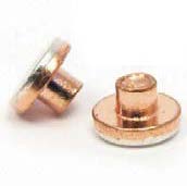
Electrical contacts are currently rivets made of pure silver, or slightly alloyed with other metals or oxides (Cadmium, Nickel, Tin,)
Silver was chosen because it is the best known conductor of heat and electricity. Contact wears by micro vaporization at each open and close cycle. This vaporization is proportional to the strength and duration of the electric arc.
The thermal conductivity of the silver allows it to quickly evacuate the peak temperature occurring during opening of the
contacts.
Its very good electrical conductivity allows for devices with very low contact resistance, generally less than 3 milliohms.
However it is not stainless and is gradually covered by a thin layer of silver oxide which is not electrically conductive.
This layer is easily vaporized during use in common household voltages (120V, 230V). However, for use in low voltage (less than 12V) and very low currents (a few milliamperes), the arc created when opening the contact is not sufficient to vaporize the contact.
This is the reason why, for low-power circuits, the contacts are protected against the oxidation by a thin layer of gold.
2.2 CONTACT GAP
After opening, the contacts are spaced by a gap. This gap, according to the device may vary from 1/10th to 3mm or more. An usual value in thermostats is 0.3 to 0.4 mm, which corresponds to micro-disconnection requested by electrical standards .
Smaller gap, which is the mechanical requirement to make low differential devices (see definition belows) cannot be used in high voltages, because, although there is no mechanical contact between the 2 contacts, an electrical arc can spontaneously appears in 380 or higher voltages: just adverse weather conditions such as high relative humidity may be sufficient.
A method to increase the contacts gap without requiring thermostats to provide significant movement, is the double break, used on some manual reset thermostats, which also reduces the risk of contact welding.
3. CONDITIONS OF USE AND ELECTRICAL LIFE
In the specifications for an electromechanical thermostat, the expected life is described in terms of mechanical and electrical.
Electrical life :
This is specified as a minimum number of cycles (action of opening and closing) will make, carry, and break the specified load without contact sticking or welding, and without exceeding the electrical specifications of the device.
Mechanical life:
This is the number of operations which a thermostat can be expected to perform while maintaining mechanical integrity.
Mechanical life is normally tested with no load or voltage applied to the power contacts, and is not part of this document.
Switch performance is influenced by a variety of factors, including: frequency of operation, type of load, temperature,
humidity, altitude. Electrical ratings are been tentatively standardized in UL 1054, CSA22.55 or IEC61058-1 (Switches for
appliances). IEC60730-x standards have specified testing methods and preferred electrical life classes for electrical control and safety switches.
These life classes are (cycles):
300 000, 200 000, 100 000, 30 000, 20 000, 10 000, 6 000, 3 000 (1), 1000(1), 300 (2), 30(2)(4), 1(3).
1) Not applicable to thermostats or to other fast cycling actions.
2) Applicable only to manual reset.
3) Applicable only to actions which require the replacement of a part after each operation.
4) Can only be reset during manufacturer servicing.
The rating tables should be considered as working maximum for most applications. Hereunder are given some limitations that apply when they are used in other loads and voltages.
The current rating of thermostat switches is given in their technical data sheets for a resistive load in 250 or (and) 400V AC and a specified number of operations. When there is enough room, these values are printed on the product. In most of case, only the minimum mandatory information is printed. The cycle number is exceptionally printed, but this is one of the most critical parameter to estimate the expected life of the thermostat.
3.1 Explanation of printed values made on a thermostat upon IEC60-730-1 § 7-2
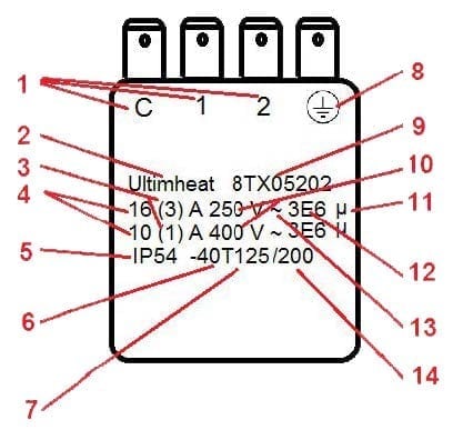
- Identification of terminals that are suitable for the connection of external conductors, and if they are suitable for line or neutral conductors, or both.
L= must be used for line in United Kingdom, other countries no restriction. N must be used if the terminals must be used for neutral ( All countries) - Manufacturer’s name or trade mark
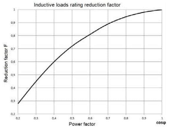
- Inductive load rating with power factor = 0.6 (When inductive load value is not printed, these contacts may be used for an inductive load, provided that the power factor is not less than 0,8, and the inductive load does not exceed 60 % of the current rating provided for the resistive load.)
- Resistive load rating with power factor = 0.95+/-0.05
- Degree of protection provided by enclosure, does not apply to controls or parts thereof classified as IP00, IP10, IP20, IP30 and IP40.
- High temperature limits of the switch head (Tmax), if other than 55 °C.
- Low temperature limits of the switch head, if lower than 0 °C
- Ground terminal identification (if existing)
- Unique type reference
- Rated voltage or rated voltage range in volts (V) (Frequency printing is mandatory if other than for range 50 Hz to 60 Hz inclusive)
- Micro-disconnection (reduced contact gap) Printing is not mandatory.
- Number of cycles of actuation for each manual action (For manual reset thermostat).
Number of automatic cycles for each automatic action (for control thermostat). Printing is not mandatory - For use on alternative circuit, 50 to 60Hz inclusive
- Temperature limits of mounting surfaces (Ts) if more than 20 K above Tmax
3.2 VOLTAGE, RESISTIVE OR INDUCTIVE CIRCUIT, SHIFTING ANGLE (cos phi)
In Europe, the most common voltage is 230 Volts AC 50Hz. In general, all devices are designed for these conditions.
400V operation must match particular contact spacing. However, particular attention must be given to the type of load to control: Electrical ratings are always given for a resistive load (cos phi=1). Applications with inductive loads like motors, transformers, coils, ballast, or capacitive loads, like capacitors on one or 2 speed motors cause much more important electrical arcing between contacts . These inductive or capacitive loads severely limit the contact rating.
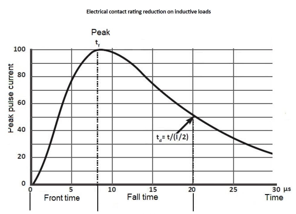
Overvoltage peak on inductive load circuits
When a switch breaks an inductive load, a fairly high counter electromotive force (counter emf) is generated in the switch’s contact circuit. The higher the counter emf, the greater the damage to the contacts.
The quantity of electrical current which flows through the contact directly influences the contact’s life. Impulse voltage is the critical value which the switch must withstand when the voltage surges momentarily due to switching an inductive load. They generate a current surge wave, witch form has generally a pulse width of 20 to 50 μs. Surge pulse rating is specified by its intensity and its width. Pulse width is time measured from pulse start to decrease to 50% of its maximum current value.
Figure shows a 8/20μs rated curve.
Motors loads impulse voltage:
During start-up, a motor can pull 600% or more of its running current. Thus, a 3 amp motor may actually pull 18 amps or more during start-up. Additionally, when disconnected, a motor acts as a voltage generator as it slows to a stop. Depending on the motor, it can feed back into the circuit voltage well in excess of rated line voltage. These voltages appearing across the separating contacts can cause a destructive arc to exist between the contacts, which can lead to early failure of the contact.
Lamp loads impulse voltage:
A tungsten filament lamp, when filament is cold, has an initial inrush current of 10 to 15 time the nominal current.
Transformers inductive loads:
When power is removed from a transformer, its core may contain remanent magnetism. If power is reapplied when voltage is of the same polarity as that of the remanent magnetism, the core may go into saturation during the first half-cycle of reapplied power. As a result, inductance will be minimal and an inrush current of perhaps 1,000% may exist for a few cycles until the core comes out of saturation. Also, as with motor loads, when power is removed from a transformer, the transformer will develop a counter voltage which can cause a destructive arc to exist between separating contacts.
Distributed line capacitance loads:
This occurs when a switch is located a considerable distance from the load to be switched. The instant the contacts close,
distributed line capacitance charges before load current flows. This capacitance can appear as an initial short circuit to the
contacts, and can pull a current well in excess of load current.
Average inductive loads correction factor(if no arc suppression device is used)
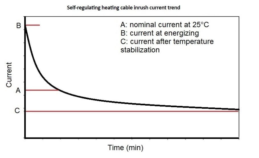
Self-regulating cables inrush current surge
This is a completely different effect than short transient currents due to the contact switching interaction with the load.
This current surge is due to the PTC design of self-regulating cable and takes several minutes to dissipate.
Often the heating cable will be at a relatively low temperature (and hence low resistance) when initially energized. The low
resistance will thus draw a high start-up current, inversely proportional to the ambient temperature. It can reach 2 times the nominal value given at 25°C by the manufacturer
Refer to records of cable manufacturers to check the inrush current value.
Indicative average current rating reduction coefficients (AC)
| Resistive load |
Filament lamp** |
Electromagnetic | Transformer |
Single phase motor |
Three phase motor | Self-regulating heating cables* |
| 1 | 0.8 | 0.5 | 0.5 | 0.12/0.24 | 0.18/0.33 | 0.6 |
* Average value, depending on cable ambient temperature at startup, see the manufacturers manuals and Standard CEI60898
** with hot filament
Average electrical life of a thermostat switch rated 15A250V, 300.000 cycles
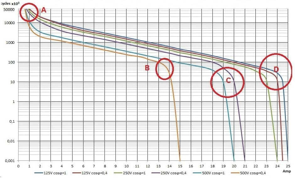
Average approximate values for a snap action mechanism with silver contacts.
Characteristic points:
A: Zone of mechanical break of the contact blade by metal fatigue
B: Contacts fast melting zone due to combination o inductive current, high voltage and high intensity
C: Zone of contacts rapid deterioration due to huge arcs
D: Zone of contact damage due to heating of the contact blade by the Joule effect and the loss of its elastic characteristics, combined with the electrical arcs
3.3 AC AND DC
In the alternative current, the voltage crosses zero in each cycle, causing the arc extinction.
In DC circuits the contact does not pass a zero voltage.
So, the arc will extinguish only when the contacts gap becomes large enough to break the arc (a phenomenon used in arc welding equipment).
In thermostats the contact gap is generally low, from 0.3 to 0.5 mm.
In voltages higher than 48VDC, this contact gap is insufficient to extinguish the arc, which continues through the electrical conductivity of the ionized air caused by the passage of current.
Contacts wearing is then extremely fast, and contacts can melt or weld in a few cycles, because the unidirectional flow of current causes a transfer of metal between the contacts
Any application requiring the use of a thermostat in a DC circuit above 48V should be studied carefully, in collaboration with the supplier of the thermostat, so that reliable technical solutions (increased contact gap, magnetic blow of the arc or other contact protection) can bee implemented.
DC Indicative breaking capacities reduction on snap action silver contacts, with the same lifetime, in resistive circuit
| Current | 0.2 mm contact gap | 0.25 mm contact gap | 0.5 mm contact gap |
| AC, 250V | 15 | 15 | 15 |
| DC, 8V | 15 | 15 | 15 |
| DC, 30V | 2 | 2 | 6 |
| DC, 120V | 0.4 | 0.4 | 0.5 |
| DC, 230V | 0.2 | 0.2 | 0.25 |
HIGH FREQUENCY
High frequency applications should be avoided, because they initiate overheating loops in contact blades, which anneals them and modify their flexibility. The contact blade loses its snap action contact and contacts weld or have a premature wear.
3.4 CYCLING SPEED AND NUMBER OF CYCLES
Electrical contact life is, as we have seen above, the result of many factors.
It is important that the contact has time to evacuate the heat due to the electric arc. Too fast cycling (more than 0.5 per second) cause premature wear, since the contact can not evacuate the rise in temperature.
Most thermostats are designed to withstand:
• 100 000 cycles in control devices.
• 10 000 cycles in safety devices.
In some applications the number of cycles can be much lower. A device designed to withstand 100,000 cycles at 1A can withstand 25A for a few hundred cycles, and even 100 or 150A for 1 cycle.
Expected life and cycle is a very important parameter to know for the determination of a thermostat.
3.5 CONTACTS PROTECTION (capacitors, filters, varistors, magnetic blow)
It is possible, by means of accessories external to the contact, to extend or improve its longevity.
These systems are all designed to limit the duration of the arc.
•The oldest is the capacity mounted in parallel to the contact, which allows to use it in DC. This solution was extensively used some decades ago, when there were still domestic DC power supply. It is effective and inexpensive.
•The filter (Inductance and capacitor assembly) is mainly used on slow break contacts to avoid radio interference. It significantly increases the electrical life.
• More recently discovered, Varistors, absorb surges created by contact opening, and limit the arc duration and intensity. They double or triple the life, especially in inductive circuits.
• The magnetic blow, little used, is intended only for DC currents. A strong magnet located around the contact area, deviates the ionized arc, and makes a longer path that extinguishes the arc. This is the solution for high power ratings in 120 and 230V DC loads.
• Inductance: This system is mounted in series with the switch in the immediate vicinity of the contact. When it is well engineered, it has a smoothing effect on the voltage peaks.
3.6 CONTACTS CONTAMINATION
The presence in the atmosphere of a number of chemicals may have an adverse effect on the contacts operation and life.
In particular:
• A high relative humidity: more intense arcs, because the air loses some of its insulating properties
• Presence of ammonia : oxidation of contact blades, which are made of copper alloys.
• Presence of silicone oil or vapors: silicone on the contacts stops the electrical current, because when silicone is burned by the electric arc, it becomes silica (aluminum oxide), which is a high temperature resistant insulator.
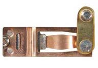
3.7 CONTACT SYSTEMS CROSSED BY THE CURRENT
In some small devices (temperature limiting), the contact mounted bimetal strips are themselves the temperature sensing elements.
These strips are not, because of their composition, very good conductors of electricity. The current flow in them causes them to heat by Joule’s effect, and this temperature comes to be added to the temperature measurement. This is named « current sensitivity » and « thermal drift » in calibration.
3.8 CONTACTS OXIDATION
We have seen above that the contact resistance was very low, of the order of a few milli-ohms. Whatever the current passing through it, the resistance is too low to cause significant heating. However, if for one reason or another (contamination, oxidation, insufficient contact pressure, mechanical deformation, etc..), the contact resistance increases, this resistance will heat the contacts if the current is high, and may overheat them enough to melt or burn flammable materials located nearby.
4. CONTROL ACTIONS
4.1 TEMPERATURE CONTROL
This the first function of a thermostat. A temperature control action contact is a contact that will cycle periodically, by opening and closing an electrical circuit. This is not a safety device. Contacts must withstand a high number of cycles.
4.2 THE AUTOMATIC RESET
The automatic reset is a temperature limiter function that does not require, in case of tripping, the intervention of an operator. This type of contact is intended to warn of a malfunction and avoid product destruction if the control device is not working or broken. It resets when the temperature returns to permitted limits.
The current number of cycles of operation of this type of action is between 300 and 10 000.
4.3 THE MANUAL RESET
A manual reset is a temperature limiting function, which requires, in case of tripping, the intervention of an operator to reset the device. This type of contact is intended to warn of a malfunction and protect the product by shut off the electrical power. The reset can be done when the temperature is returned to the authorized limits. Manual reset can be accessed or hidden. In general, they cannot be reset without using a tool or without removing a cover or a cap.
The current number of cycles of operation of this type of action is between 300 and 10 000.
4.4 ELECTRICAL RESET
This is the same function as above, but there is no reset button. It automatically resets after disconnection of the power supply.
4.5 RESET BY TEMPERATURE DROP
Temperature drop reset is an automatic reset after a significant drop in temperature, generally close to the ambient temperature.
This solution is very little used.
4.6 THE “ONE SHOT”
The “one shot” is a type of contact that can only be opened once. Its use is typically that of ultimate safety device, which definitely cut the power supply. Restarting the application needs a full replacement of it. Its number of operating cycles is 1. This function can be performed by metal alloy melting, plastic pellet melting, glass bead break, triggering of a bimetal disc whose return to the starting position is not possible even in the coldest ambient temperatures.
4.7 FAIL SAFE
Fail safe is a positive auto control of the device. Any leakage or breakage of the temperature sensing device causes the electrical power shut-off. This function is difficult to define in bimetal thermostats (discs, rod, bimetal), but for thermostat using a bulb and capillary assembly, it defines the mode of operation when it leaks.
The fail-safe mechanisms in bulb and capillary thermostats
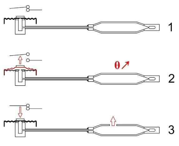
Diastat Standard Operation:
Position 1: a standard diastat is shown in the starting position, at room temperature.
In position 2: the temperature of the sensor has reached the set point, and the inflation of the bellows caused the opening of the contact, stopping heating.
In position 3: the bulb (or capillary) leaks, the bellows deflates, the electrical contact closes, and the heating is switched on again.
But no further expansion is transmitted to the bellows, and nothing can stop nor regulate heating. This is the dangerous situation that failsafe systems must obviate.
Positive safety is primarily used on manual reset thermostat, installed after a standard temperature control unit.
There are two fail safe systems with a different mode of operation, each system having its own advantages and disadvantages.
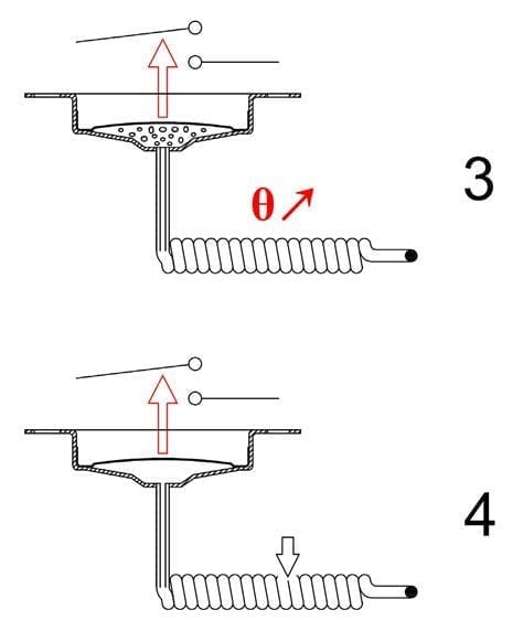
Liquid expansion type failsafe systems
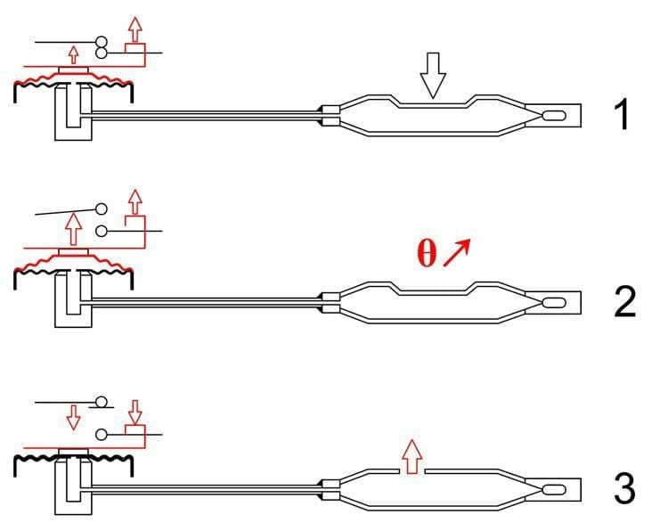
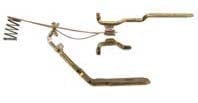
In these systems, after sealing the diastat at ambient temperature, a small bump is made on the bulb, causing an artificial inflation of the bellows (1). It is also possible to produce the same function by sealing the diastat at a negative temperature (-20, -30 ° C). By these ways the bellows continues to contract at temperatures below room temperature.
When the temperature on the bulb increases (2), the movable part of the electrical contact is actuated by the bellows. When the bulb or the capillary is leaking (3) the bellows is deflated under the thickness it has at ambient temperature, and an auxiliary mechanism (in red) displaces the fixed part of electrical contact out of reach of the movable part, thereby opening the contact.
This positive safety system allows easy adjustment of the thermostats trigger temperature, because the mechanism is similar to an adjustable thermostat, and calibration can therefore cover the entire temperature range of these adjustable thermostats.
However, it has two issues:
• The artificial increase of the bellows significantly increases the volume of liquid inside thereof, and thus increases its sensitivity to the ambient temperature on the thermostat head.
Examples of calibration point drift on a manual reset thermostat with 1.5 m capillary, calibrated at 90 ° C
| Type of mechanism | Set point drift with head temperature at 0°C | Set point drift with head temperature at 50°C |
| With fail safe | 90+8,1 | 90-9.5 |
| Without fail safe | 90+5,5 | 90-6,5 |
• When the ambient temperature falls under the freezing point, the bellows continues to contract, and can unexpectedly actuate the safety.
This type of false tripping is supervised by the EN60730 standard, which sets the minimum ambient temperature without triggering at -15 ° C.
However, when using these thermostats in areas with ambient temperature lower than this limit, it is necessary to warm up the thermostat bulb around 20 ° C to reset the safety when it has triggered.
Boiling style failsafe systems
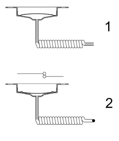
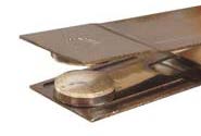
In boiling type fail safe systems, the bellows of the diastat consists of two dishes, one of which is bumped.
This bumping is of convex shape, as a bimetallic disc, and snaps from convex to concave when subjected to a force. The diastat, before filling (1) is constructed so that the cup is in the unstressed position is outwardly bulged.
The diastat is then filled with thermostatic liquid under vacuum, then sealed with the cup pushed inwards (2). In this position, the electrical contacts are closed.
In case of temperature rise, the liquid boils at the temperature determined by its composition. The substantial increase in volume caused by the boiling causes the change of shape of the cup, which snaps outwards and opens the contact (3). Upon cooling of the liquid, the force produced by the diastat and required for bumping inwards the cup is insufficient, and it is necessary to press it with a reset button to restore it to its inward form.
In case of punctures or leaks in the diastat, the liquid inside is set to the atmospheric pressure, and the cup snaps outwardly.
This system is particularly simple, reliable, and requires no complicated mechanism. It is not sensitive to the ambient temperature on the capillary or on the head, does not trigger unexpectedly when ambient temperatures are too low.
It has, however, like the previous one, two flaws:
• Triggering temperature depends of boiling liquid used (Generally mixtures of water, glycol and alcohol), and therefore they are practically limited to values between 60 and 170 ° C.
• They are sensitive to atmospheric pressure and set point varies slightly with altitude.
5. MULTIPLES CONTACTS
5.1 CHANGE OVER CONTACTS (SPDT, for: single pole double throw)
The changeover contact is a contact with three terminals.They are a common, a normally closed contact and a normally open contact. During actuation, the contact switches from one position to another. This allows for example to switch off the heating and simultaneously turning on ventilation.
5.2 SIMULTANEOUS CONTACTS
Simultaneous contacts are independent contacts, with synchronous action.
This is particularly important in cutting a three-phase circuit devices, because the cut of the three phases must be done at the same time.
5.3 STAGGERED CONTACTS
These contacts are operated by the same measuring system, but at different temperatures.
5.4 NEUTRAL ZONE CONTACTS
These contacts are parts of the staggered contacts, but with no electrical action between their set points. Their particular application is the air conditioning or refrigeration.
For example the contact # 1 switches off the heating at 100 ° C, the contact # 2 will turn on the vent at 120 ° C. Between these two temperatures, no action will be required: this is the neutral zone.
5.5 ADJUSTABLE DIFFERENTIAL CONTACTS
The differential is the temperature difference existing between the moment the device actuates (opens) a contact and when, as a result of the drop in temperature resulting from its opening action, it resets.
Depending on the type of contact, these differentials can have huge span.
The adjustable differential is a system that allow the user to change it.
For technical reasons and cost, adjustable differential mechanism is reserved for industrial type systems using gas expansion.
5.6 MIXED CONTACTS
Mixed contacts by means of a combination of different systems above.
The most common combination is a control and a reset contact, or or a control and and a one shot contact.
5.7 FLAMEPROOF CONTACTS
A flameproof contact is a contact does not allow the electric arc that it produces to ignite an explosion outside its enclosure.
The electrical arc is not deleted.
There is a difference between the devices whose only the electrical contact is protected and those whose entire mechanism is protected.
5.8 FLAMEPROOF ENCLOSURE CONTACTS
In these devices only the mechanism of the electrical contact is protected by a flameproof enclosure. The electrical connections are made at the end of a cable secured to the casing of the contact area and must be made outside the hazardous area, or in a suitable connection box.
This solution provides small devices, and low cost.
5.9 FLAMEPROOF ENCLOSURES
Flameproof enclosures are massive envelopes where the entire device is enclosed. Electrical connections can be made inside the envelope.