Useful technical tables for air heating
1. Sheated tubular heating elements technical data
Figures provided in this section are results of tests made in our laboratory. Charts were smoothened by computer, and are given for specified power and for information only.
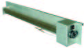
Type 3AY
| Estimated life expectancies for magnesium oxide insulated heater types made in stainless steel or refractory alloys | |||||||
| Surface temperature | Time (years) | Time (hours) | Surface temperature | Time (years) | Time (hours) | ||
| °C | °F | °C | °F | ||||
| 700 | 1300 | 23 | 200.000 | 980 | 1800 | 0.15 | 1200 |
| 760 | 1400 | 9 | 80.000 | 1040 | 1900 | 0.01 | 360 |
| 815 | 1500 | 3.5 | 30.000 | 1095 | 2000 | – | 180 |
| 870 | 1600 | 1 | 8700 | 1150 | 2100 | – | 48 |
| 925 | 1700 | 0.3 | 3000 | ||||
For a standard sheathed element, the surface temperature of 870 °C (1600 °F) is the maximum temperature to insure expected heater life greater than one year. These values are for information only, and data are provided for heating elements usgin Nickel Chrome alloy wire whose cross section is optimized, and which are insulated with good quality pure magnesia, not contaminated. This deterioriation of heating wires at temperatures well below their melting point is due to chemical reactions that occur at high temperature between the iron oxide (which is a contaminant of magnesia), and the wire itself.
Note: When the sheathed elements are used in medium infrared radiant heating, this temperature of 870 °C (1600°F) is generally exceeded if the surface load is equal to or greater than 10W/cm² (60W/in²). This is the main reason of the short life expectancy of these heaters in this application.
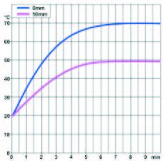
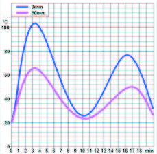
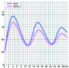
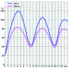
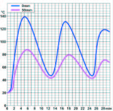
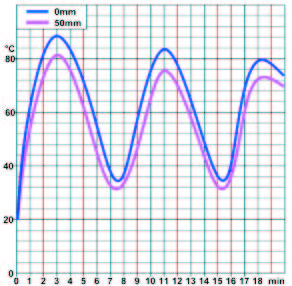
Average surface temperature and average air temperature of air heaters described in this catalogue
Temperture cycles of some tables are due to built-in temperature controls.
Figures provided in this section are sresults of tetst made in our laboratory. Charts were smoothened by computer, and are given for specified power and for information only.
| 9SR, P7 | 9SX, P8 | 9NN, P10, 400W | 9NF, P11, 4000W | 9SQ, P12, 500W |
 |
 |
 |
 |
 |
 |
 |
 |
 |
 |
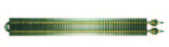
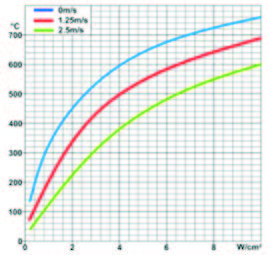
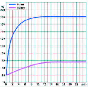
| Surface temperature of a dia. 10 mm stainless steel sheathed tubular heating element, VS surface load, in still air, and in ventilated air. (RT=20°C) |
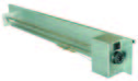
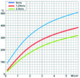
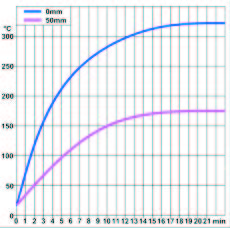
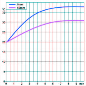
Surface temperature of a stainless steel finned heater, 25 x 50 mm fins, VS surface load, in still air, and in ventilated air.(RT=20°C) |
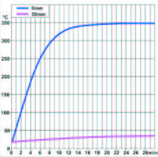
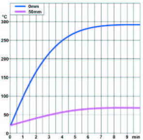
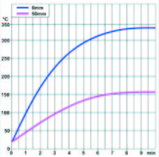
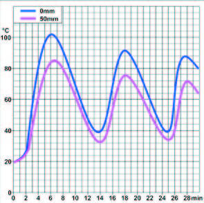
Surface temperature of a compact duct heater, and temperature measured at 50 mm from the air outlet grid, air speed 2m/s | Fins surface temperature of a medium power duct heater, and temperature measured at 50mm from the fins, air speed 2m/s | Surface temperature of remodeling sheathed heater, and temperature measured at 50mm from the sheathed element, natural convection |
| 9SY, P13, 1050W | 9PF, P14, 100W | 9CG1, P15, 3000W | 9CG3, P16, 4000W | 9CH,P17, 3000W |
 |
 |
 |
 |
 |
 |
 |
 |
 |
 |
| Surface temperature of remodeling finned sheathed heater, and temperature measured at 50 mm from the fins, natural convection |
Surface temperature of cabinet heater, and temperature measured at 50 mm from the air outlet grid, air speed 2m/s | Outlet grid surface temperature of enclosed finned heater, heater, and temperature measured at 50 mm from the air outlet grid, natural convection |
Outlet grid surface temperature of an enclosed finned heater, and temperature measured at 50 mm from the air outlet grid, natural convection |
Outlet grid surface temperature of an enclosed finned fan heater, with thermostat control, and temperature measured at 50 mm from the air outlet grid, air speed 1m/s |
| 9CL, P18, 1500W | 9CJ, P20 | 9CK, P21, 4000W | 9CR, P22 | 9CS, P23, 4000W |
 |
 |
 |
 |
 |
 |
 |
 |
 |
 |
| Outlet grid surface temperature of an enclosed finned fan heater, downward blowing, with thermostat control, and temperature measured at 50 mm downside the air outlet grid, air speed 1m/s | Outlet grid surface temperature of an enclosed finned fan heater, with thermostat control, and temperature measured at 50 mm from the air outlet grid, air speed 2m/s |
Outlet grid surface temperature of an enclosed finned fan heater, with electronic control, and temperature measured at 50 mm from the air outlet grid, air speed 2m/s |
Outlet grid surface temperature of an enclosed finned fan heater, downward blowing, with thermostat control, and temperature measured at 50 mm downside the air outlet grid, air speed 2m/s | Outlet grid surface temperature of an enclosed finned fan heater, downward blowing, with electronic control, and temperature measured at 50 mm downside the air outlet grid, air speed 2m/s |
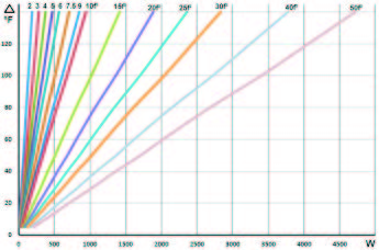
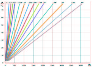
Indicative power selection chart of cabinet heaters (Non insulated metal cabinets)
|
|
2. Infrared heating elements technical data
2.1 Infrared wavelengths
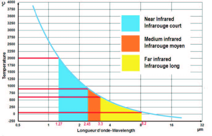
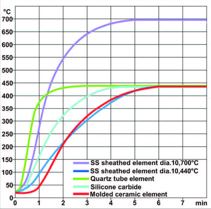
| Infrared heater surface temperature VS wavelength | Response time of different far infrared heaters (temperature stabilized at 440°C), compared to response time of a medium infrared heater (temperature stabilized at 700°C). |
 |
 |
There are many definitions of infrared and its division into far (long), medium and near (short), and often confusion is made between these different definitions.
–The first is that of astronomy, according to ISO 20473 which defines the infrared radiation from the red edge of the visible spectrum at 0.780 micrometers (microns) up to 1000 microns.
–The second is that of the CIE recommends that in the field of photobiology and photochemistry, cutting the infrared range into three zones: IR-A: 0.7 microns to 1.4 microns; IR-B: of 1,4 microns to 3 microns; IR-C: 3 microns to 1000 microns.
– The third, used in the field of infrared heating, defined wavelengths as follows (see table below):
- Far infrared, from 370 to 600°C, corresponding to a wavelength of 4.5 to 3.30μm.
However, there are infrared emitters called “low temperature infrared” for space heating (heating ceilings, wall heating for saunas, convectors called “radiant” heaters), which operate at lower surface temperatures of about 70 to 80 ° C corresponding to wave lengths from 8.2 to 7.8 microns. - Medium Infrared, 600 to 900°C corresponding to a wavelength of 3.3 to 2.45μm
Far Infrared Emitters.
– Infrared ceramic heater made of a ceramic encapsulated wire. The surface temperature of the ceramic may range from 350 °C to 650 ° C. Because of their design and the low thermal conductivity of the ceramic used, differences in temperature up to 200°C on the emissive surface between bumps and groves, center and edges are possible. The resulting infrared radiation is distributed over a large wavelength range. In addition, a large percentage of the radiation emitted on the rear face of such elements, only serves to heat their support.
The ceramics used to make these elements have a low emissivity in the far infrared, so, an additional percentage of the energy is dissipated in the different wavelengths. To overcome it, some of them are now covered with a black glaze. The time to reach 90% of their operating temperature, starting from 25°C is approximately 5 minutes 40s).
–Sintered silicon carbide tube emitters: they reach an emissivity close to 100% in the 3 to 4 microns wavelength, corresponding to 450 – 690°C (840-1280 ° F) surface temperature. The time to reach 90% of their operating temperature, starting from 25°Cn is about 3 minutes 30 seconds.
– Sheathed tubular elements: usually consisting of a tube made of Inconel, specially oxidized to give it a better infrared emissivity. The tube surface gives a dark red visible radiation. Their surface temperature range from 450 to 600°C. The time to reach 90% of their operating temperature, starting from 25°C is about 5 minutes 30 seconds for a 10 mm dia. tub. (About the same time than a ceramic radiant heater).
Medium infrared emitters
They come in two main forms:
– Quartz tube elements, in which a wire coil, made of chromium nickel, carbon, iron-nickel-chromium or tungsten, is placed in a milky surface quartz tube. These tubes are open at both ends, and in contact with atmospheric air. They have a surface temperature of 700°C to 1000°C; Particularly economical, but fragile, with a limited life of about 5000 hours for the heating wire reaching high temperatures in air where they are quickly oxidized.
The time to reach 90% of the operating temperature, measured from 25 ° C is approximately 1 minute 20s).
– Tubular sheathed elements, similar to those used in the far infrared. The high surface load gives a visible red light. The surface temperature of these components is in the range of 700 ° C to 800 ° C.
The time to reach 90% of the operating temperature, measured from 25 ° C is approximately 2 minutes 40s.
Near (Short) Infrared emitter
This radiation source is constituted by an incandescent tungsten or Iron-Chromium-Aluminum filament in a quartz tube filled with nitrogen or argon and, optionally, depending on the model, a small percentage of halogen gas. The filament is heated to an average temperature of 1800°C. (Some up to 2500°C). Originally developed for applications in lighting, they emit a portion of their radiation in the far infrared, as a part of the emitted wavelengths in the visible spectrum and in the near infrared is absorbed by the quartz and converted in far infrared by the silica-oxygen chemical bond.
Their inertia is very low (a few seconds). These tubes must be cooled.
2.2 The main types of infrared emitters
Materials are selective as to the wavelength accepted to absorb infrared energy. Most of materials show a peak of absorption between 3 and 4 microns (μm).
The wavelength produced by the heat source is dependent upon the source temperature. It is possible then to adjust the source temperature and thus the peak wavelength to match the best spectral absorption rate or wavelength. The formula providing surface temperature for a requested wavelength (μ) is:
°C=(2897/μ)-273 or °F= (5215/μ)-459
For example, if the product to heat has an absorption peak at 3.5μ, the heating element surface temperature should be: (2897/3.5)-373 = 555°C, or (5215/3.5)-459 = 1031°F.
This rule applies no matter what the construction of heat source.
Hence, filament bulb temperatures being very high, they will radiate in the near infrared, sheathed incolloy heaters with temperatures of 600 to 700 ° will radiate in the mid Infrared, and ceramic heaters with 400 to 500°C surface temperature will radiate in the far infrared. What will make the difference in the final efficiency is the percentage of power supplied to the heating source that will be converted in the required wavelength.
This also means that it is possible to adjust the wavelength peak of a radiating source by controlling its surface temperature, e.g by adjusting the voltage or controlling the power, and mainly using heaters materials with the best emissivity in the requested wavelength.
Sintered silicon carbide tubes reach a radiance near 100% equivalent to a blackbody) in the 3 to 4 micron zone corresponding to 450 – 690°C (840-1280°F) surface temperature.
2.3 Thermal response of silicone carbide infrared heaters
 |
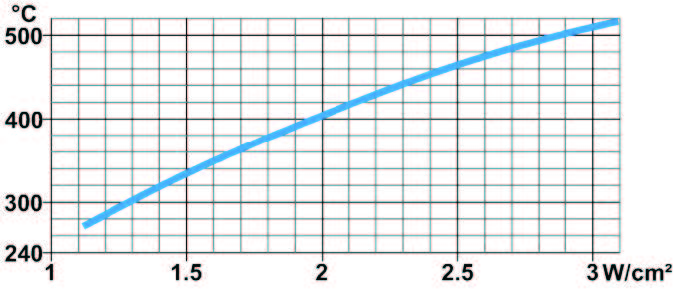 |
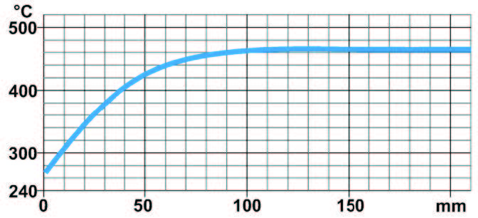
| Surface temperature of a silicon carbide infrared heater, measured at center, vs watt/cm² | Surface temperature of silicon carbide infrared heater vs ends distance. Both ends are cooler than center and radiate in a longer infrared wavelength |
2.4 Some Material Emissivity
| Emissivity | Emissivity | Emissivity | Emissivity | ||
| Polished Surface | Black Oxided | Polished Surface | Black Oxided | ||
| Aluminium | 0.09 | 0.22 | Incoloy 800 | 0.20 | 0.92 |
| Brass | 0.04 | 0.60 | Incoloy 600 | 0.20 | 0.92 |
| Copper | 0.04 | 0.65 | Sintered Silicone oxide | N.A | 0.93 |
| Stainless 304, 316, 321 | 0.17 | 0.85 | Blackbody | N.A | 1.00 |
2.5 Absorption peak of some materials (μm)
Absorption peaks are wavelengths that are the most converted in energy inside the material and will result in its heating.
| Absorption peaks ofinfrared radiations | Material | ||||||
| Water | Aluminium | Linen, cotton | Concrete | Silk | Plaster | Porcelain | |
| Main peak wavelength(μ) | 3 | 3 | 3 | 3 | 3 | 3 | 5 |
| Secondary peak wavelength (μ) | 6 | 8.5 | 6.5 | 6.5 | 5 | 6 | 8 |
| Flint, Crystal | Polyethylene | Plexiglass | PVC | Polystyrene | Magnesium oxide | Rubber | |
| Main peak wavelength(μ) | 8 | 3.5 | 6 | 3.5 | 3.5 | 3.5 | 3.5 |
| Secondary peak wavelength (μ) | N/A | 7 | 9 | 7 | 7 | 6 | 8 |
2.6 Temperature of food products heated by infrared emitter
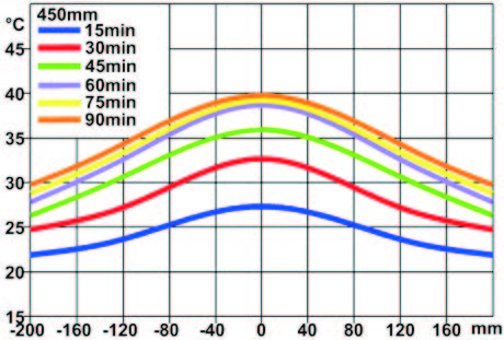
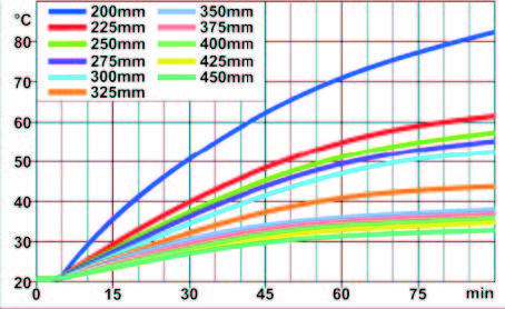
Tests carried out by subjecting a 30mm thickness sample of synthetic material (methylcellulose gel) having a UV behavior close to food. Test made from different distances, by measuring the sample temperature at 10mm deep. Tests were made with silicone carbide infrared heaters 9MH described p19 in this catalog. The distance is measured from the edge of the reflector to the surface of the sample. Sample temperature is 20°C at the start of the test.
 |
 |
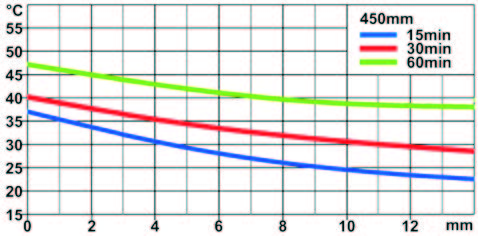 |
| Temperature from center to edges, after different time, for 450mm distance between sample and heater |
Average temperature at center of sample vs time, a different distances between sample and heater |
Heat penetration inside sample after different heating times, 450mm distance between sample and heater |