6: Adjustment system
7: Electrical connection
8: Protection housing (Option)
9: Spring cap (negative pressure only)
10: Spring (negative pressure only)
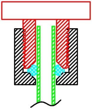
The pressure switches of this catalogue are made according to the flexible elastomeric membrane technology.
The pressure applied deforms the membrane which then actuates an electrical contact.
A counter-pressure system, which force is provided either by the contact system itself or by a spring, is applied to the membrane to adjust the set point.
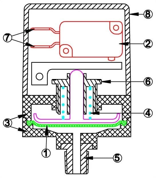
Positive pressure, snap action type
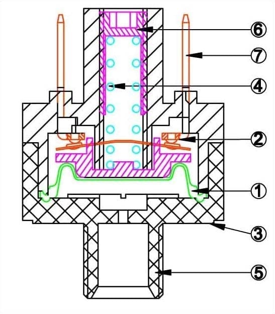
Positive pressure, creep action type
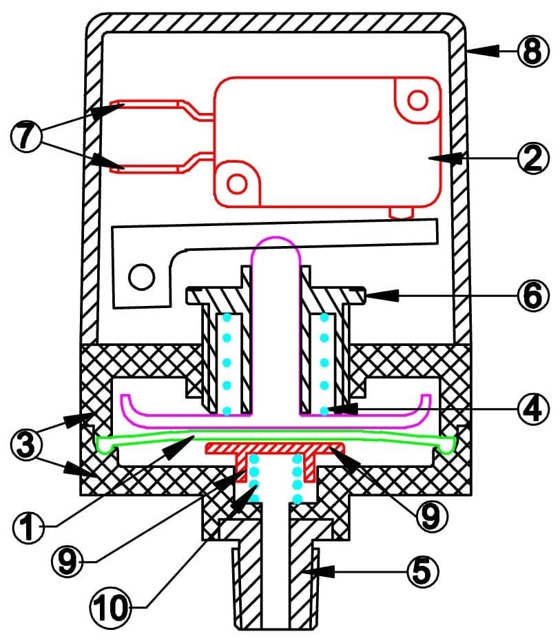
Negative pressure, snap action type
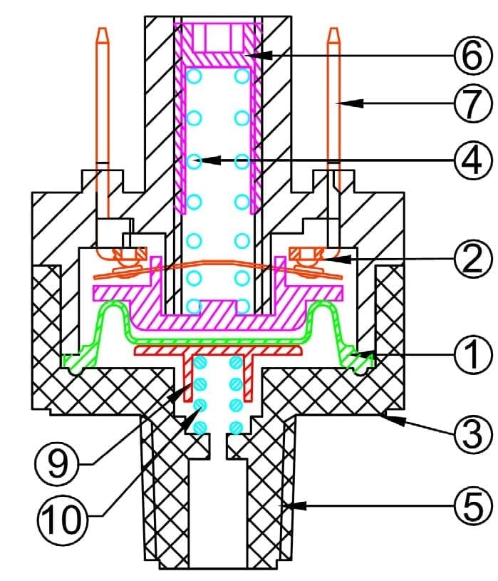
Negative pressure, creep action type
1: Membrane
2: Electrical switch
3: Pressurized body
4: Back pressure spring
5: Pressure inlet
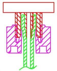
Differential pressure switch, creep action type
6: Adjustment system
7: Electrical connection
8: Protection housing (Option)
9: Spring cap (negative pressure only)
10: Spring (negative pressure only)
-The membrane area: to a givne pressure, the larger the membrane area, the greater the force with which the membrane pushes the contact system.
-The membrane flexibility: it is essential for the realization of switches that are measuring low pressures below 0.1 MPa (1 bar). Elastomers used mustbe flexible and resilient. In general, the lower the pressure is, the more flexible the membrane must be for fine sensitivity.
-The membrane thickness: the thin membranes cannot withstand high pressures. The thickness of the membrane will be
optimized to give the best sensitivity while resisting the maximum pressure to which it may be subjected in operation. The
maximum pressure limit can vary from 0.05 MPa to 1 MPa depending on the models and thicknesses.
The temperature resistance of the membrane: Compared to metal diaphragms, elastomeric membrane have the advantage of flexibility, allowing the use for low pressure measurements. Elastomers are still limited by their temperature (usually not more than 85 ° C in constant temperature), although it is possible, under certain conditions to use silicone membranes that offer greater thermal resistances (up to 125 ° C or more).
– The chemical resistance of the membrane: The type of elastomer must be compatible with the nature of the fluid or liquid with which the membrane comes into contact.
In addition, it must not harden or crack over time. The gas or liquids in contact with the membrane can have a corrosive or destructive effect on short, medium or long term on it, eg ozone, chlorine and its compounds, bromine and its compounds.
The chemical composition of the membrane and how it is vulcanized or molded are the parameters that will influence this resistance.
Contact with drinking water: In some applications, when the float is in contact with drinking water, health standards are added, which regulate the chemical composition. The highest standards known, that are used as a normative reference in many countries are
those issued by the FDA (Food and Drug Administration, USA) and the WRC (water research council, GB). These standards provide particularly the maximum permissible surface in contact with water and the maximum temperature at which the plastic may be exposed without harmful compounds are released into the water. The WRC also tests elastomers to ensure that they do not facilitate the spread of bacteria
– The number of membranes: some countries and safety standards require two membranes, especially for applications where
the switch is in contact with water or people can be immersed. This solution is available in most JPC products however it reduces
the accuracy of the pressure switches.
A certain force is required to actuate the electrical contact device. It can range from a few grams for systems with creep action contacts, to several hundred grams for snap action micro-switches.
In general, the force required to operate an electrical contact increases with its electrical rating.
Creep action contacts
In apparatus slow breaking both sides deviate slowly at speeds of the order of 1/10 mm per second.
In the normal atmosphere, then occurs when the contacts are close together, an electrical arc.
The length of this arc is a function of voltage.
For voltages up to 24V DC or 110V AC, the duration of this arc is short, less than 0.1s.
For higher voltages, the arc lasts much longer, producing premature fusion of the contact, and many radio interference.
This is why it is not recommended, despite the mechanical advantages (simplicity, low cost, high precision) to use this contact in 230V networks to control multiple cycling applications.
| Their disadvantages: | Their advantages: |
| Do not allow to cut high amperages due to the large arcs (and the radio interference which are the consequence) that occur between the contacts when they are in close proximity to each other. As electric arcs increase with voltage, they are generally not used for voltages above 24V. |
-Inexpensive |
| – There are no slow break pressure switches with a change-over contact, they are usually designed to close the contact when the pressure rises (normally open contact NO), but some models are available with a contact which opens with increasing pressure (normally close contact, NC). |
– Low operating force allowing the use for low pressure values. |
| – Low differential values between high and low pressure switching levels. |
|
| – Easy and inexpensive making of gold-plated contacts for use in low voltage. |
Snap action contacts
On snap action switches, the contact opening speed is around 1m per second (100.000 faster).
The contact spacing reaches the distance to extinguish the arcing in less than 1/1000 sec. Therefore there is no radio interference, and the contact does not deteriorate. Mechanically, this type of contact, also called “energy storing contact” is much more complicated, expensive, and does not allow such a great control than reed switches.
The snap action micro switch is particularly suitable for devices operating at 240 or 400 V.
| Their disadvantages: | Their advantages: |
| – Expensive | – High ratings in 110 and 230V, up to 30A. |
| – Large actuating force limiting their use in low pressure or requesting the use of large diameter membranes |
– NO, NC or SPDT contacts |
| – Large differential travel on the switch, affecting the accuracy of pressure control and providing important distance in high and low pressure switching levels |
– Snap action contacts do not generate EMC |
Silver contacts, gold plated contacts:
The contact of a micro-switch wears by micro vaporization at each open and close cycle. This wear is proportional to the strength
and duration of the electric arc.
The most common contact material is pure or alloyed silver. This material was chosen because it is the best conductor of heat and electricity known.
Its thermal conductivity quickly evacuates the temperature peak occurring during these cycles.
Its very good electrical conductivity provides very low contact resistance, usually less than 3 milli-ohms.
However it oxidizes and is gradually covered with a thin layer of silver oxide, which is not electrically conductive.
This layer is easily vaporized when the switch is used in common household voltages (240V, 300V). However, when used in low voltage (less than 12V) and very low currents (a few milli-amps), and less than 800mW, the contact opening arc is no longer sufficient to vaporize the silver oxide layer. The solution is to plate the contact with a thin layer of gold (said gold flash) 3 to 5 microns thick, to ensure its protection.
Comparison of contact materials and plating
| Silver and silver alloys | Gold plated silver |
| – High electrical rating, mandatory use for electrical rating higher than 1A 250VAC |
– Cannot be used on voltages lower than 0.1 millivolt, because the contact resistance is too high |
| – Oxidize and the contact resistance increases with time if they are used to cut electrical rating less than 20V and 100 mA | – The use on voltages higher than 30V and / or with currents above 100 mA causes vaporization of the gold flash protection. Then the contact behaves like a standard silver contact |
| – Cannot be used in oxidizing atmosphere | – If the load is less than 30 mV and 10 mA, there is no change in the contact resistance and the electrical life becomes very important (except atmospheric contamination by hydrocarbon) |
The pressurized body consists of two half-shells which enclose a membrane. It must meet several constraints
Use in contact with drinking water: when plastic is in contact with drinking water, sanitation standards require that it does not release harmful chemicals into the water. The standards and accepted concentrations differ by country, but all give a maximum operating temperature of plastic materials related to temperature. If an application requires compliance to these standards, it is necessary to provide the standard to be met and the maximum water temperature at which the switch will be submitted.
We, at JPC, always make the back pressure spring in stainless steel to withstand various environmental media encountered in
applications.
When a switch is subjected to a pressure greater than that for which it was designed, the back pressure spring, or the contact mechanism will be subjected to high stresses that can cause a permanent deformation and thus, result in the set point change of the device.
The connection can be done according to several basic systems
DESCRIPTION
DRAWINGS
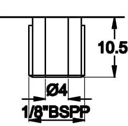
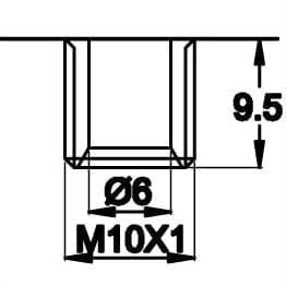
By a plastic thread. The most common are M10 x 1, 1/8 NPT, 1/8 BSPT, 1/8 BSPP, 1/4 NPT, 1/4 BSPT, 1/4 BSPP. This system is frequently used to control pressure of liquids.
Cylindrical
Conical
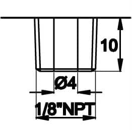
By a metallic thread. The most common are M10 x 1, 1/8 NPT, 1/8 BSPT, 1/8 BSPP, 1/4 NPT, 1/4 BSPT, 1/4 BSPP. This system is frequently used to control pressure of liquids.
Cylindrical
Conical
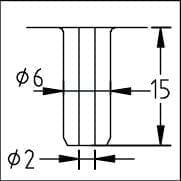
By a fluted or smooth spout for 6x3mm flexible tubes and other diameters. This system is frequently used to control air pressure or vacuum, and for pneumatic remote controls. This solution must be used for low pressure, less than 250 mBars.
Parallel thread
Taped thread
By a smooth spout dia. 6 mm for “Push in” fittings (ISO14743)
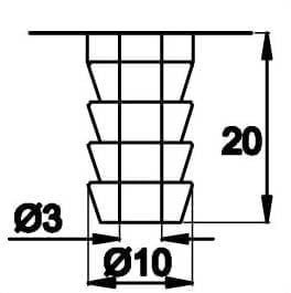
By a barbed spout for flexible PVC tubes. This system is frequently used to control pressure or air in pneumatic control systems.
Pressure limited to 500mbar
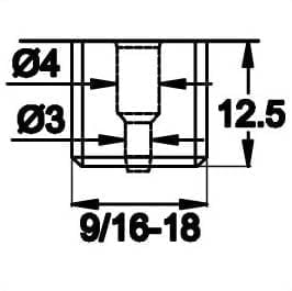
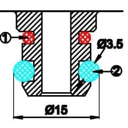
With a threaded spout, with O-Ring gasket compressed by a nut on a soft or hard tube
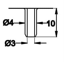
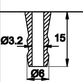
With a smooth spout for 6x3mm flexible tubes and clamping nut.
This solution is used in air switch tubing. Maximum pressure 1 Bar (0.1 MPa)
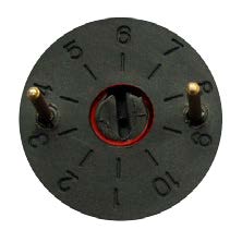
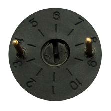
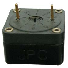
Adjusting a pressure switch is made by a force opposed to the movement of the membrane actuating the electrical contact system. This force is produced by a spring which is more or less compressed depending on the setting value to obtain. There are three possible settings:
DESCRIPTION
SCHEMA
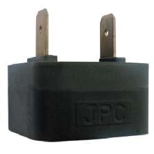
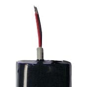
DESCRIPTION
PICTURE
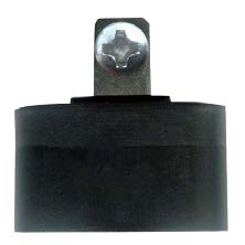
Pins for printed circuits
Screw terminals
Tabs
Lead wires
The protection housing can have two functions:
– Ingress protection against attacks from the outside environment (rain, dust, shock)
– Protection against the conditions in which the product will be installed in its application.
In most cases, pressure switches will be integrated by an OEM into a machine or equipment. Then it is this machine or equipment that will ensure protection against water, dust, shock and other contaminants.