Technical introduction of connection blocks made in ceramic and polyamide
Introduction
The problem of the temperature resistance of the ceramic terminal blocks is only very slightly addressed by the existing standards. If the porcelain terminal blocks, the first ones to have been developed at the beginning of the 20th century, used ceramic as an insulating material, it was because there was no other economical electrical insulating material that could be molded at the time. and having sufficient mechanical strength. Temperature resistance in domestic electrical installations was a secondary parameter.
Gradually, however, ceramics have given way to plastics in everyday applications. Ceramic (porcelain and steatite) is only used in applications where mechanical strength and resistance to high temperatures are preferred and cannot be achieved with thermoplastics or thermosets.
The standards write little of these applications, and the T200 marking provided in some is insufficient for ceramics.
While some obvious test exemptions for ceramic insulators are provided for in electrical standards, these do not differentiate between types of ceramics, and their insulating properties at high temperatures are ignored. It is the same for the temperature resistance of the metals used for the electrical terminals.
In recent years, there has been a need for increasingly high temperatures, far above 200 ° C, for example the fire resistance standards for cables: NFC3270,
IEC 60331, EN50200, DIN VDE 0472 part 814, BS 8434-2, BS 6387 A, B, C, S etc.
These standards have different temperature resistance values, ranging from 650°C for 30min to 950°C for 180 minutes.
The few scattered information of standards for resistance to high temperatures are insufficient: for example the standard EN60730-1 (controls for household appliances) gives a maximum ceramic temperature of 425°C in §14-1; 200°C on 6.35 nickel-plated brass tabs, and 230°C for un-plated brass terminals; 400°C to steel … More, there is no mention of special temperatures for nickel.
In order to correctly quantify the possibilities of the ceramic terminal blocks, we thought it would be useful to give the engineering departments appropriate technical elements.
First section : Insulation parts of connection blocks
Electrical and mechanical characteristics of ceramics used in connection blocks
The different ceramics used in terminal blocks and electrical insulating parts are distinguished by their composition, their method of manufacture, and especially by their insulating capacities (resistivity) as a function of temperature. In terminal block applications, their high frequency dielectric characteristics are not an important criterion. All these ceramics are of course non-flammable, and classified with a comparative tracking index (CTI) greater than 600 in electrical standards, this is the highest class of resistance to surface currents. The reference standard for these ceramics is IEC (EN) 60672.
The ceramics of the C100 group
The basic components of Ceramics group C100 (Alkaline aluminio silicate porcelain) are quartz, feldspar and kaolin, which are similar to decorative and household porcelain.
The C111 Porcelain: It is a pressed siliceous porcelain with an open porosity of not more than 3% and whose dielectric strength varies according to the compression. It must be glazed to overcome its porosity.
It has an excellent electrical insulation at room temperature (1011 ohms.m at 30°C), its insulation is still correct at 200°C (106 ohms.m), but its resistivity drops sharply to 300°C to be only 100 ohms.m at 600°C.
It is the oldest of the electrically insulating ceramic materials. It was traditionally used as early as the end of the 19th century to make electrical insulating parts for low-temperature domestic applications: Switches bases, lamp sockets, conductor supports, electrical terminal blocks. When enamelled, it is easy to clean. The molds are simple, and easy to produce with rudimentary equipment. But if it is perfectly suitable for use up to 200°C, its use becomes hazardous above because of the rapid loss of its insulating properties. Expensive in manual manufacturing time, difficult to automate, it is still used in low salary-price countries. The dimensional tolerances are wide, and the rate of rejects per crack due to unequal compression is important.
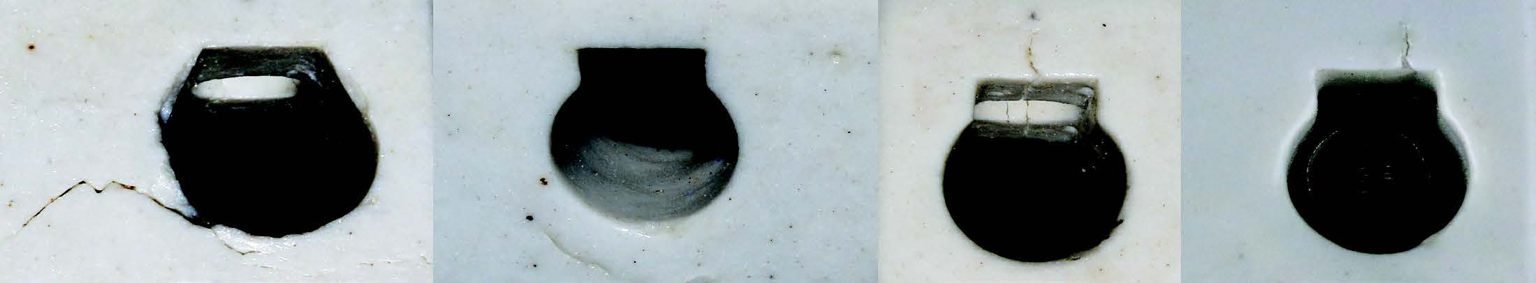 |
|||
| Examples of cracks on C111 porcelain |
C110 Porcelain: This is a plasticized porcelain which can be injection molded. Its dielectric strength is excellent, of the order of 20KV/mm. As it is non-porous, it does not need to be enamelled except for reasons of ease of cleaning.
Its insulating characteristics in temperature are the same as the C111, that is to say 1010 ohms.m at 30°C, 106 at 200°C, and as well, the resistivity drops brutally towards 300°C to reach 100 ohms at 600 ° C.
The steatites of the C200 group
Steatites are distinguished from porcelain by their high percentage of magnesium oxide (MgO), of about 26 to 32%, the remainder being mainly silica (SiO2) and fluxes. It is a material with a strong dielectric, highly insulating at high temperature, and it remains stable up to more than 1000°C.
Typical production processes are dry pressing, extrusion, casting and semi wet pressing. It is also molded by injection, in plastified form, and allows tight tolerances.
The material is fired at around 1400°C and steatite is formed by crystallyzation, fusion and dissolving during the vitrification. To obtain a contamination free and easy to clean surface, steatite can also be glazed.
Steatite C210 so-called low frequency steatite, is little used in electrothermal terminal blocks. It is obtained by semi-wet pressing and must be enamelled because its porosity is of the order of 0.7%. It retains good insulating properties even at 600°C (1000 ohms.m).
The Steatite C220, also called normal steatite, with zero porosity, is a steatite comprising 1 to 2% of Na2O and 3 to 6% of alumina and flux. Like C210, its resistivity is 1010 ohms.m at 30°C, 107 ohms.m at 200 ° C and 103 ohms.m at 600°C.
The steatite C221, also known as high-frequency steatite, has zero porosity and differs from C220 by adding 7% Barium oxide (BaO). Highly insulating at room temperature (1011 ohms.m), it has the best resistivity at 600°C: 100000 ohms.m, a thousand times more than porcelain. It can be injection molded, with high precision. It is therefore the ideal material for terminal blocks that must withstand high or very high temperatures. It can be used raw or enamelled if appears the need for a smooth surface.
The ceramics of the C600 group
The low alkali C610 aluminous ceramic, also known as Mullite, has a high percentage of alumina (Al2O3), of about 60% and the remainder of silica (SiO2). Its porosity is zero. Its temperature resistivity and good, including up to 600°C (10000 ohms.m). Its good resistance to thermal shocks, its high mechanical resistance, its low coefficient of expansion and its good resistance to thermal shock, make it preferable for the realization of insulators of heating resistors, as well as for the protection tubes of the temperature sensors. Because of molding difficulties, it is not used in connection blocks.
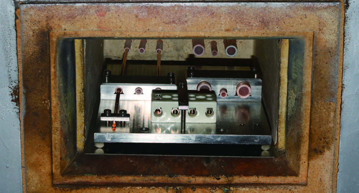 |
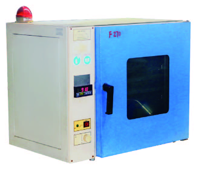
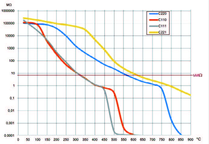 |
| Test oven for the resistivity of ceramics as a function of temperature (Ultimheat Laboratory) | Insulation resistance variation curves of terminal blocks as a function of temperature, made in different types of ceramic, (C110, C111, C220, C221), in thickness 2mm. The value of 5MΩ is the normative limit. |
Maximum temperature of ceramic in terminal blocks
Electrotechnical ceramics have very high temperatures with temperatures up to 1400°C, 1700°C or even higher. However, in electrical terminal block and insulator applications, the critical parameter is insulation resistance.
IEC 60998 provides a minimum insulation resistance of 5 MΩ between live parts and between live parts and earth-contactable parts, such as a mounting plate. This isolation resistance depends on:
- the thickness of the insulation where it is the
- the temperature.
The design of our ceramic terminal blocks provides, where this thickness is the weakest, that is to say between the fixing screws and the electrical terminals:
- minimum 1.2mm wall thickness for terminal blocks up to 250V.
- minimum 2mm wall thickness for terminal blocks up to
- minimum 3mm wall thickness for terminal blocks up to
Given these values, and depending on the resistivity variation of ceramics as a function of temperature, the limit values we recommend are:
- For ceramic C111: 250 ° C
- For ceramic C110: 300 ° C
- For C220 steatite: 550 ° C
- For C221 steatite: 650 ° C
Limit values have been safely selected to be 100°C below the threshold of 5 MΩ (for a 2mm thickness wall).
Electrical and mechanical characteristics of plastics used in connection blocks
The plastic material of this terminal block, a particular high-end PA66, has been selected to meet the specific constraints of its use.
The most critical constraint that a terminal block can undergo, is a poor tightening of a conductor, the high contact resistance of which causes the terminal to overheat and to melt the plastic material of the support. The class providing the highest resistance to overheating and that of plastics with a GWFI (Glow Wire Ignition Rating) greater than 850°C. This class is mandatory for applications with unattended use, according to the specifications of EN60335-1 § 30-2-3-1.
The material we use for these terminal blocks has a GWFI of 960°C, well above the minimum specifications of this standard. This plastic also offers the best resistance to tracking currents with a CTI> 600 (Class 1, the highest).
Another critical parameter, for these housings intended for these connection blocks, designed for use in hot ambient temperature, is the temperature of deflection under load. Measured according to ISO 75, this plastic material has a particularly high deflection temperature of 282°C under a 1.8 MPa load.
|
Material |
Heat deflection temperature under load according to ISO 75 | Flammability according to UL94 | Mechanical strength according to ISO 572-2 | Glow wire flammability index (GWFI), according to IEC 60695-2-12 |
| 25% Fiber glass reinforced PA66 (Black) | 282°C (1.8 Mpa) | UL94 VO and UL94-5V depending of thickness |
150 Mpa |
960°C |
Heat deflection temperature under load according to ISO 75-2
Determination of the temperature of deflexion under load upon ISO75-1 and 3, is an important parameter to judge of the ability of a plastic raw material to withstand a temperature rise without loosing its mechanical strength. This value is requested by some appliances and commercial standards. To select the best material to use in plastic connection blocks, the tests have been made under 1.8 MPa load applied at the center of the 10mm width, on 80 x10 x 4mm specimen (Method Af), The 4mm thickness has been selected as being, in the standard choice, the nearest value to the thickness used on connection blocks. The temperature rise is 2°C per minute.
The final temperature is registered when the deflection has reached 0.34mm.
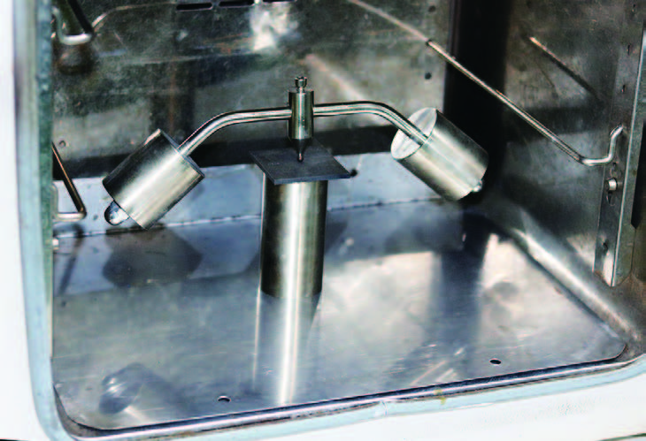
Heat deflection temperature under load according to ISO 75
 |
 |
| Test Equipment (Ultimheat Laboratory) | Specimens being tested (Ultimheat Laboratory) |
The maximum allowable temperature of PA66 connection blocks (the “T” marking)
The maximum permissible temperature on a terminal block is determined by the mechanical strength of the parts that support the terminals through which the current flows. For this it is considered that the terminals can heat up by Joule effect when they are crossed by the current. And this maximum heating value, required by standards EN60998 or EN60947 is 45°C in addition to the ambient temperature. This mechanical strength of the plastic material is measured by testing according to IEC 60695-10-2. This standard measures the penetration of a 5mm diameter ball under 20N force for one hour at the test temperature. The indentation made by the ball cannot exceed a diameter of 2mm. Consequently, a terminal block marked T200 ensures the good holding in place of parts through which the current flows when they are at a temperature of 200°C+45°C= 245°C.
NB: For ceramic terminal blocks, this test is obviously not used, and it is the maximum temperature resistance of the metal parts that will define the resistance at room temperature.
 |
 |
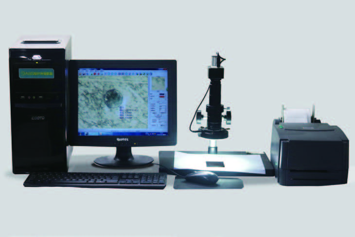 |
| Test oven (Ultimheat Laboratory) | Specimens being tested (Ultimheat Laboratory) | Electronic microscope measurement of the indent diameter (Ultimheat Laboratory) |
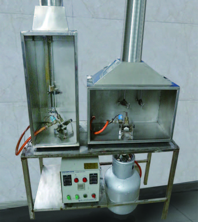
Flammability checking according to UL94, made in our laboratory
The flammability test of the plastics of the connection blocks is intended to verify that the accidental ignition of these will not spread and that the ignition will extinguish itself. The class usually required by certification laboratories is UL94-VO, or for some special cases, the highest class, UL94-5V.
 |
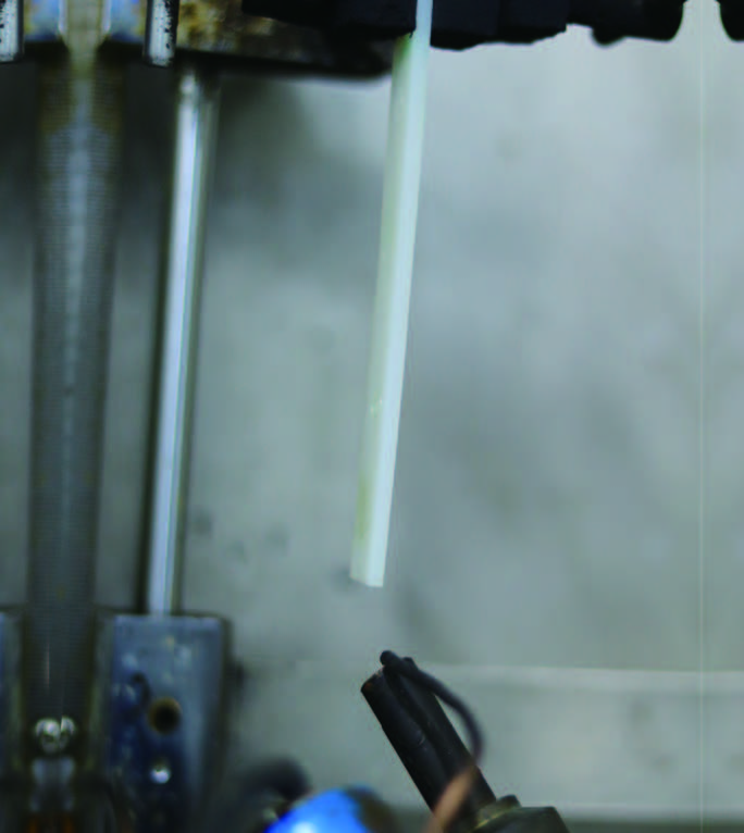 |
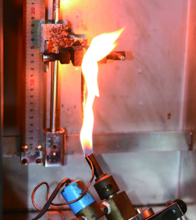 |
| Testing equipment | Specimen before testing | Specimen during UL94VO checking |
Second section: Conductors and wires
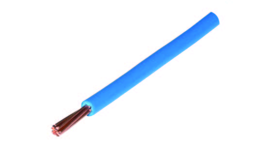
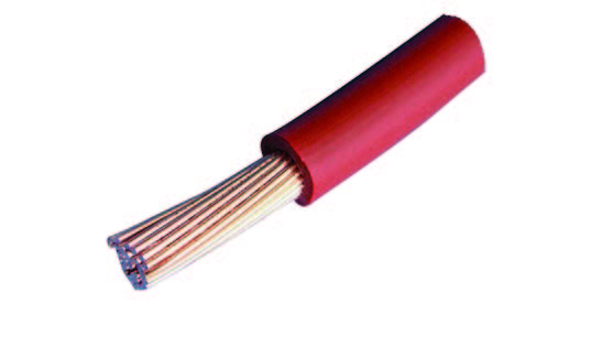
Electric cable types according to the composition of their cores
 |
 |
 |
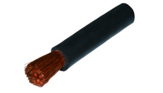 |
| Class 1, solid core | Class 2, stranded core | Class 5, flexible core | Class 6, Ultra-flexible core |
The standard IEC 60228 (1978) divides the cores of electrical conductors into four main classes:
Class 1, solid core: the core is formed by a single wire, and is usually made in cross-section limited to 6 or 10 mm² maximum. This type of conductor is intended for fixed installations
Class 2, stranded core for fixed installations: used for cores with a cross section larger than 6 or 10 mm2, the core is made up of several medium size wires. This type of conductor is intended for fixed installations
Class 5, flexible core: the core is made of many fine threads. This type of conductor is intended for connecting mobile equipment.
Class 6, Ultra-flexible core with greater flexibility than Class 5.
The terminals, depending on their nominal cross section, must accept the connection of conductors of classes 1, 2, 5, 6. unless different characteristics are given by the manufacturer.
Unless specifically marked, a terminal intended for a given maximum section must be capable of receiving solid or stranded conductors (classes 1 and 2) of this section, and flexible conductors (classes 5 and 6) of the section immediately below. For example, a 10mm² terminal block can receive a 10mm² conductor in class 1 or 2, and a 6mm² conductor class 5 or 6.
Correspondance of metric and AWG dimensions of electric conductors
To standardize the different existing standards defining sections of electrical conductors that have coexisted for decades, such as AWG,(also called Brown and Sharp), Birmingham, SWG (British Imperial Standard), Washburn & Moen etc., the international standard IEC60228 has defined the following cable gauges: 0.5 mm2, 0.75 mm2, 1 mm2, 1.5 mm2, 2.5 mm2, 4 mm2, 6 mm2, 10 mm2, 16 mm2, 25mm², 35mm², 50mm²etc. .., up to 1000mm².
Exact equivalences in mm² of AWG wire gauges for solid wires
| AWG | Diameter (mm) | Cross section (mm²) |
| 24 | 0.510 | 0.205 |
| 23 | 0.575 | 0.259 |
| 22 | 0.643 | 0.324 |
| 21 | 0.724 | 0.411 |
| 20 | 0.813 | 0.519 |
| 19 | 0.912 | 0.653 |
| 18 | 1.02 | 0.823 |
| 17 | 1.15 | 1.04 |
| 16 | 1.29 | 1.31 |
| 15 | 1.45 | 1.65 |
| 14 | 1.63 | 2.08 |
| 13 | 1.83 | 2.63 |
| 12 | 2.05 | 3.31 |
| 11 | 2.3 | 4.17 |
| 10 | 2.59 | 5.26 |
| 9 | 2.9 | 6.63 |
| 8 | 3.25 | 8.37 |
| 7 | 3.65 | 10.55 |
| 6 | 4.1 | 13.30 |
| 5 | 4.65 | 16.77 |
| 4 | 5.2 | 21.15 |
Standardized correspondence of cross-sections in mm² of metric electrical conductors with AWG sections
|
The EN60998 standard gave equivalences for terminal clamping capacities between mm² and AWG standards. |
|||||||||
| mm² | 1.5 | 2.5 | 4 | 6 | 10 | 16 | 25 | 35 | 50 |
| AWG | 16 | 14 | 12 | 10 | 8 | 6 | 4 | 2 | 0 |
Tightening torques in N.m for screw terminals according to EN60998 (for the models used in the terminal blocks of JPC)
| M2.6 | M3 | M3.5 | M4 | M5 | M6 | M8 |
| 0.4 | 0.5 | 0.8 | 1.2 | 2.0 | 2.5 | 4 |
Third part: The metallic parts of connection blocks
Electric terminal materials
The usual materials of the electric terminals are: brass, steel, stainless steel, nickel. Their selection in a connection block is determined by three main factors:
- Resistance to electrical current flow “the resistivity”, at different operating
- The variation of the mechanical resistance as a function of the temperature, this is a critical parameter for terminal blocks operating high and very high temperature.
- The cost of the raw material and of its
Resistivity to the current
Any electrical terminal in which an electric current goes through is heated by the Joule effect. The larger the current section, the lower the resistance. The longer the length between the clamping screws of the conductors, the more resistance will increase. This logical rule is the basis of the design of the terminals. The second parameter is the resistivity, expressed in Ohms.m which is highly variable depending on the materials. The inverse of resistivity is conductivity, expressed in Siemens/m, which is also sometimes given in comparison to that of copper (in % of IACS). It can be noted that stainless steel has a conductivity more than 12 times lower than brass.
Another characteristic of these metals is an increase in their resistivity when the temperature rises. This parameter must be calculated carefully when designing the terminal cross-section when the operating temperature is high.
Table of resistivity and conductivity at 20°C of main metals used in connectors
| Units | Copper | Brass CuZn40Pb2 | Nickel | Steel | Stainless steel Aisi 304 |
| Resistivity ρ at 20°C, (10-8 Ω. m) | 1.67 | 7.1 | 8.7 | 14.3 | 73 |
| Conductivity σ, at 20°C, in 106 Siemens/m | 5.8 | 1.4 | 1.15 | 0.7 | 0.14 |
| Conductivity in % IACS (International Annealed Copper Standard.) | 100% | 24% | 20% | 18% | 2% |
Ultimate Tensile strength change versus temperature
| Compared variations in ultimate tensile strength at break of copper, brass UZ34Pb2, SPCC cutting steel, stainless steel Aisi 304 and Nickel 201 according to the maximum exposure temperature maintained during 90 minutes (in% of the value measured at room temperature) |
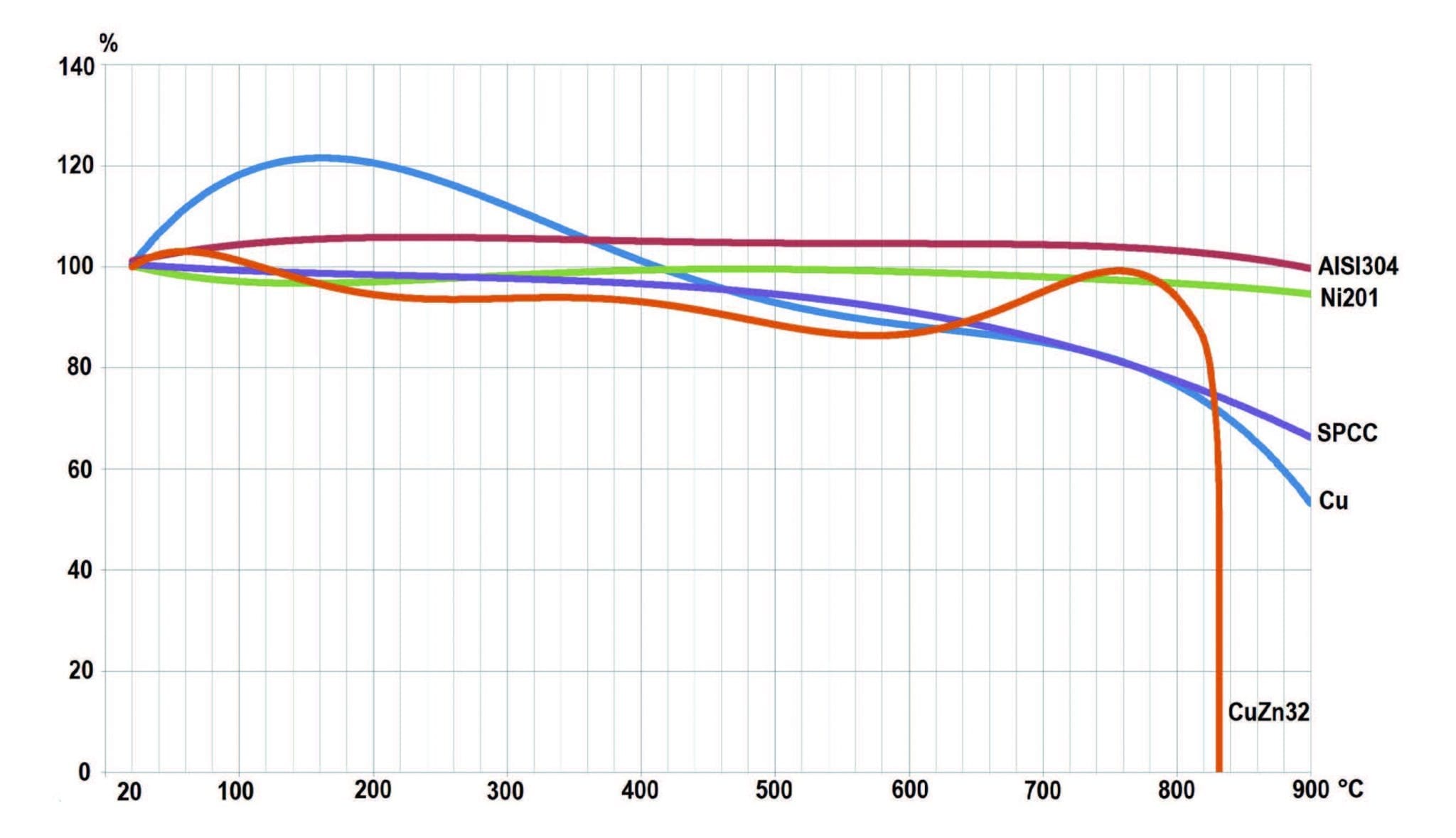 |
| Copper and steel gradually lose their mechanical strength to retain only about 50% around 900°C. Brass remains relatively stable but reaches its melting point shortly before 900°C. 304 stainless steel and nickel 201 show no significant variation in their mechanical strength up to 900 C. |
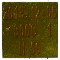
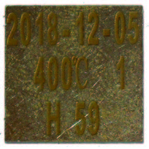
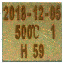
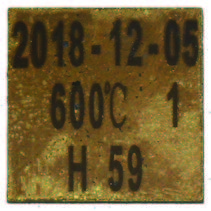
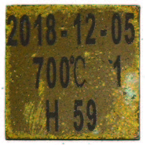
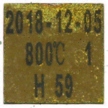
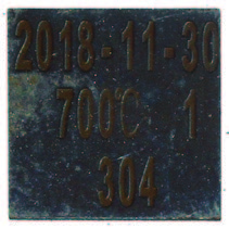
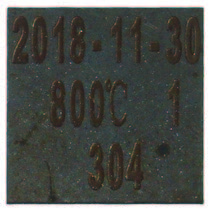
The oxidation of metals according to the temperature
| Appearance of specimens of brass, nickel-plated brass, nickel-plated steel, Aisi 304 and Nickel 201 after exposure for one hour at different temperatures, in an electric oven, under oxidizing atmosphere. | ||||||||
|
Material |
Exposure temperature |
|||||||
| 200°C /
392°F |
300°C /
572°F |
400°C /
752°F |
500°C /
932°F |
600°C /
1112°F |
700°C /
1292°F |
800°C /
1472°F |
900°C /
1652°F |
|
| Brass | 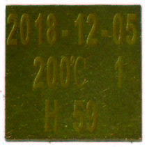 |
 |
 |
 |
 |
 |
 |
 |
| Steel (SPCC) | 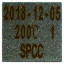 |
 |
 |
 |
 |
 |
 |
 |
| Copper |  |
 |
 |
 |
 |
 |
 |
 |
| Aisi 304 |  |
 |
 |
 |
 |
 |
 |
 |
| Nickel 201 | 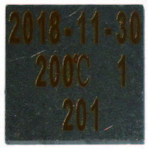 |
 |
 |
 |
 |
 |
 |
 |
| The oxide layers become unacceptable for copper and brass 400°C, or steel at 500° C, and for Aisi 304 stainless steel at 900 ° C. No appearance of significant oxide layer for Nickel 201 | ||||||||
Cost of raw material (Compared to low carbon cold rolled steel type SPCC)
| 1 | x 3.9 | x 8.2 | x 38 |
| Low carbon cold rolled steel type SPCC | 304 stainless steel | CuZn40Pb2 Brass | Nickel 201 |
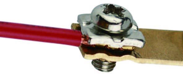
Conductor clamping styles
| Wire termination styles | Terminal style | |||||
 Screw with notched square washer Screw with notched square washer |
Direct screw |
Screw with saddle and spring washer |
 Screw with saddle, spring washer and protective tab Screw with saddle, spring washer and protective tab |
Screw with pressure plate |
||
|
Solid wire (class 1) | OK | OK | OK | OK | OK |
|
Stranded wire (class 2) | OK | OK | OK | OK | OK |
|
Flexible or very flexible wire (Class 5 or 6) | Acceptable | Not recommended | OK | OK | OK |
 |
Tinned flexible wire end* | Not recommended | Not recommended | Not recommended | Not recommended | Not recommended |
 |
Cable shoe | OK | OK | OK | OK | OK |
 |
Spade terminal | OK | No | OK | OK | No |
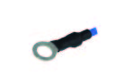 |
Eyelet terminal | OK | No | OK | OK | No |
*Clamping stranded or flexible conductors soldered together is not recommended because the tin alloy creeps.
|
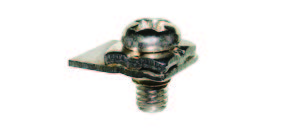
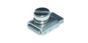
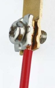
Notched square washer screw terminals (Used mainly on PA66 connection blocks and on some ceramic connection blocks) |
Depending on the size of the connection blocks, these terminals use M3, M3.5, M4, M5 and M6 screws. They feature:
- Manufacturing: very low weight of material used, very few manufacturing losses. It is therefore the most environmentally responsible
- The use of screws with a captive and enveloping square washer allows to put 2 wires inside each terminal, even with slightly different sizes without affecting the quality of tightening.
- The elastic effect of the washer also provides good resistance to loosening by vibration.
- This type of terminal allows the introduction of rigid or stranded conductors, fork lugs, eye lugs and cable shoe.
- The end of the terminal is not hidden, and makes possible to clearly visualize the correct introduction of the wire.
- The tightening of conductors, rigid or flexible is very effective, and their pull strength is significantly higher than the specifications of the standard.
- The conductive part of the terminal can be made of nickel-plated steel, raw or nickel-plated brass, pure nickel or even stainless steel.
- However, their small current passage section makes them very sensitive to Joule effect heating, especially when they are made of nickel-plated steel or stainless steel.
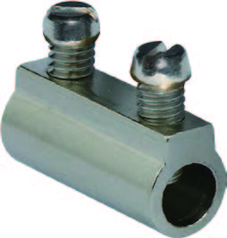 |
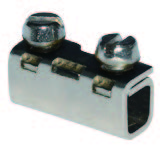
Extruded brass terminal with screw with direct clamping (only used on ceramic terminals) |
This system is the most common, and has been used traditionally for more than 100 years on ceramic terminal blocks. These terminals are machined from specially extruded CUZn40Pb2 brass bars with the required profile for each dimension.
The composition of brass (60% copper) is important to ensure a low electrical resistivity, and to avoid the fragility of the material that appears with too high levels of zinc.
They have an extra thickness in the tapping in order to have sufficient thread length to withstand the tightening torques required by the standards, and the wall thickness around the central hole must also be sufficient to prevent the tube from cracking. when tightening the screw.
However, their manufacture in a metal other than brass (stainless steel, steel) is very difficult and expensive.
- Because of the softening of brass at high temperatures, they cannot be used on high temperature terminal blocks.
- Because of the weight of metal needed with this execution, they become very expensive for gauges above 16mm².
These terminals are also limited in the number of gauges of conductors that can be tightened effectively, because the stroke of the pressure screw is limited by the round section of the hole, the screw quickly becoming locked between the walls.
 |
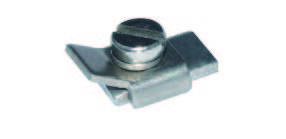
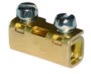
Stamped terminal with direct clamping screw (Used on ceramic terminal blocks with large sections or to withstand very high temperatures) |
Unlike parts machined from a rod, this type of manufacturing, although expensive in tooling, reduces metal losses. It is particularly economical in large sections (Above 16mm²). It can also be used to make nickel-plated steel, stainless steel or nickel terminals. It is therefore the preferred technique for the realization of terminals resistant to temperatures up to 750°C. As the conductor hole is rectangular, the pressure screw has a longer clamping stroke and this increases the range of allowable gauges.
|
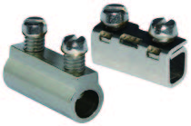
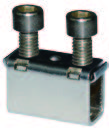
Stamped terminal with clamping screw and pressure plate (Used on ceramic terminal blocks with large sections or to withstand very high temperatures) |
Reserved for large cross-section models, this system combines a stainless-steel body or nickel body, with stainless steel cylindrical socket head cap screws. A nickel spring blade distributes the pressure. It is therefore recommended on flexible or extra-flexible conductors, of classes 5 and 6, because there is no risk of cutting the strands. The flexibility of the pressure plate maintains an optimal clamping independent of the expansions due to the temperature. These models support permanent temperatures of 750°C, and peak temperatures of 950°C.
|
Screw with saddle and screw with saddle and protective tab (Used on ceramic connection blocks) |
These terminals are used on high temperature terminal blocks because they are easily made of stainless steel. They have the advantage of being able to put two conductors under the same saddle and to fit a large range of conductor gauges. The spring washer located between the screw head and the saddle ensures the continuity of clamping, even at high temperatures and on copper conductors. However, due to the low electrical conductivity of stainless steel, the terminals tend to warm up much more than the brass or nickel terminals, which limits the maximum current they can withstand. If this limitation of the intensity is prohibitive it is recommended to use models with pure nickel terminals, but with elastic washer in stainless steel. In order to avoid cutting the wire by shearing due to the saddle edge, it can incorporate an anti-shearing tab.
Loosening terminal block screws due to temperature rise
On terminals that have to withstand high temperatures, the effect of temperature is a critical parameter that the applicable standards do not enough take into account. The most critical point is the loosening of the terminals, which by promoting the increase of the contact resistance between the terminal and the conductor, will cause a localized heating up to the ignition of nearby combustible materials. This loosening has four origins:
- The deformation of the terminal by its expansion, makes tightening This deformation is generally reversible when the temperature drops, and can be compensated by the elasticity of the terminal or a spring included between the pressure screw and the conductor.
- The deformation of the terminal by the change of crystalline structure of the metal, similar to annealing. This deformation is in general irreversible
- Deformation of the copper conductor wire, made malleable by This deformation is in general irreversible, but can be avoided by the use of conductors resistant to heat, for example nickel.
- The loosening of the pressure screw by the successive cycles of heating and cooling between different materials. Two solutions that can be implemented separately or jointly
- Insert an elastic metal part between the screw and the conductor;
- Set up a system of automatic locking of the screws caused by the deformation of the terminal during the tightening
| Average variation of the tightening torque of the terminal block screws after a short * peak of temperature. The tightening torque at 20°C is taken as 100% (The terminals are tightened on a steel rod with the maximum nominal diameter allowed for the terminal) | ||||||||||||
|
Terminal style |
Material |
Temperature | ||||||||||
| 90 minutes at 200°C | 90 minutes at 300°C | 90 minutes at 400°C | 90 minutes at 500°C | 90 minutes at 600°C | 90 minutes at 700°C | 90 minutes at 800°C | 90 minutes at 900°C | |||||
|
Full nickel plated steel |
93 |
82 |
80 |
91 |
87 |
72 |
Screw blocked by oxide | Screw blocked by oxide | |||
|
Full Stainless steel 304 |
96 |
93 |
81 |
80 |
80 |
85 |
86 |
84 |
|||
|
Nickel plated brass terminal, nickel plated steel screws |
84 |
84 |
74 |
66 |
50 |
36 |
Terminal melted |
Terminal melted |
|||
 |
Brass terminal, nickel plated steel screws |
96 |
76 |
68 |
63 |
62 |
49 |
Terminal melted |
Terminal melted |
|||
|
Full Nickel plated steel |
91 |
77 |
77 |
77 |
51 |
Screw blocked by oxide |
Screw blocked by oxide |
Screw blocked by oxide |
|||
|
Full stainless steel 304 |
95 |
91 |
81 |
78 |
80 |
86 |
88 |
84 |
|||
|
Nickel 201 terminal, 304 stainless steel screws |
95 |
91 |
81 |
78 |
80 |
86 |
88 |
84 |
|||
|
Nickel 201 terminal, nickel plated steel screws |
79 |
80 |
116 |
160 |
197 |
229
Screw is blocked |
255
Screw is blocked |
323
Screw is blocked |
|||
|
Nickel 201 terminal,
304 stainless steel screws with pressure plate |
100 |
170 |
103 |
103 |
104 |
108 |
145 |
170 |
|||
| ≥ 25% or more loss of tightening | Terminals broken, or no more usable, or torque more than 2x higher than initial. | |||||||||||
| Nickel-plated steel screws cannot be use, even for short time, at temperatures above 600°C, because the oxidation of the screw causes its blockage. For higher temperatures, only stainless steel or nickel screws are usable and remain functional, allowing disassembly and replacement if necessary. | ||||||||||||
| Average variation of the tightening torque of the terminal block screws after an extended temperature exposure at 230°C. The tightening torque at 20°C is taken as 100% (The terminals are tightened on a steel rod with the maximum nominal diameter allowed for the terminal | |||
| Material | 230°C, 48H | 230°C, 120H | 230°C, 192H |
| Nickel plated steel terminal with nickel plated steel screws | 81 | 120 | 111 |
| Brass terminal with nickel plated steel screws | 86 | 86 | 86 |
| Nickel-plated steel screws, used on steel or brass terminals, withstand 230°C in permanent temperature, without blockage and without abnormal oxidation | |||
| Average variation of the tightening torque of the terminal block screws after an extended temperature exposure at 300°C. The tightening torque at 20°C is taken as 100% (The terminals are tightened on a steel rod with the maximum nominal diameter allowed for the terminal | |||
| Material | 300°C, 48H | 300°C, 120H | 300°C, 192H |
| Nickel plated steel terminal with nickel plated steel screws | 70 | 68 | 65 |
| Brass terminal with nickel plated steel screws | 62 | 60 | 60 |
| We do not recommend the use of nickel-plated steel screws on brass or nickel-plated steel terminals, for permanent temperatures above 300 ° C due to the loss of tightening torque | |||
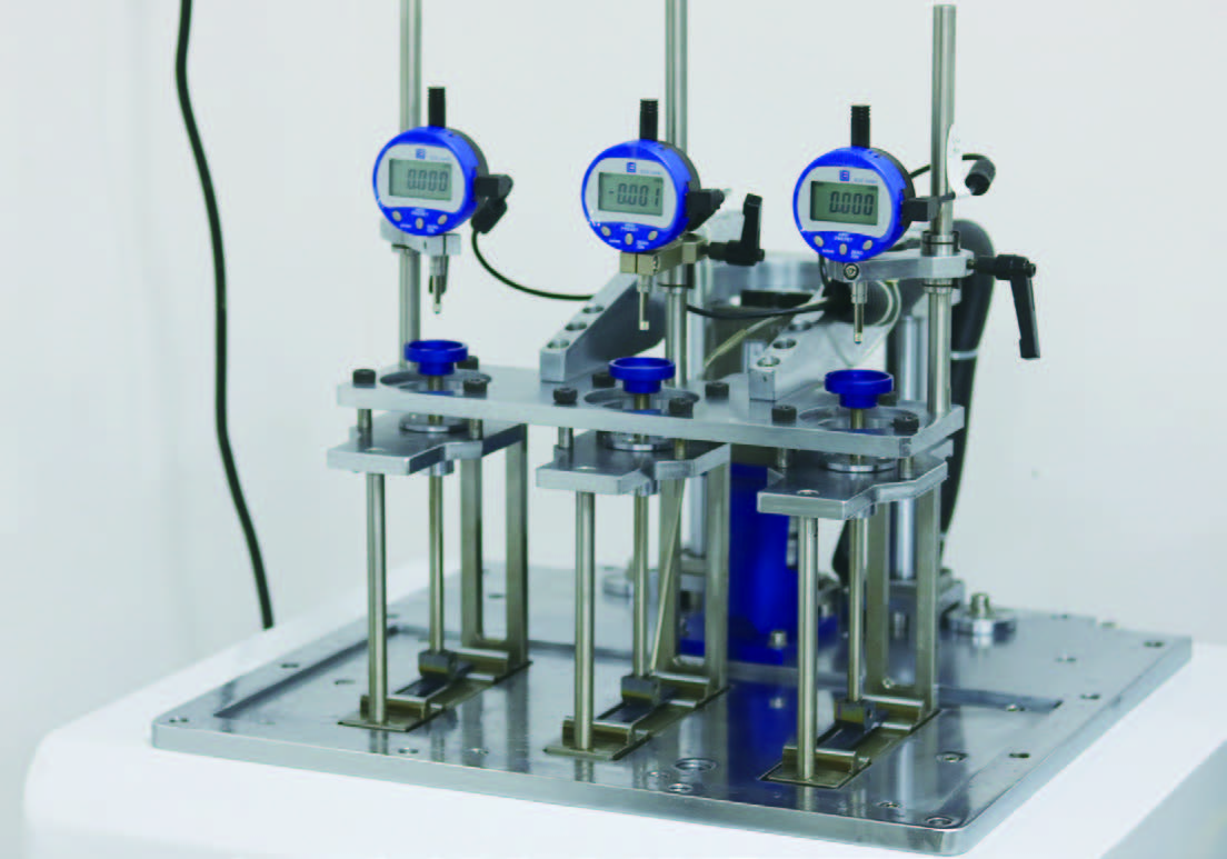
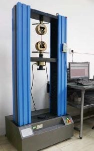
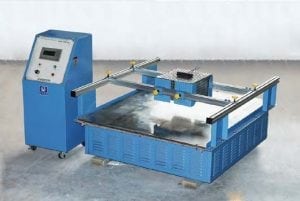
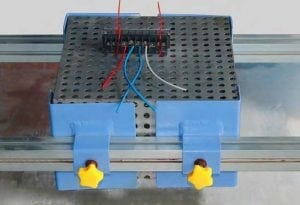
Wire pull-out force and vibration loosening resistance
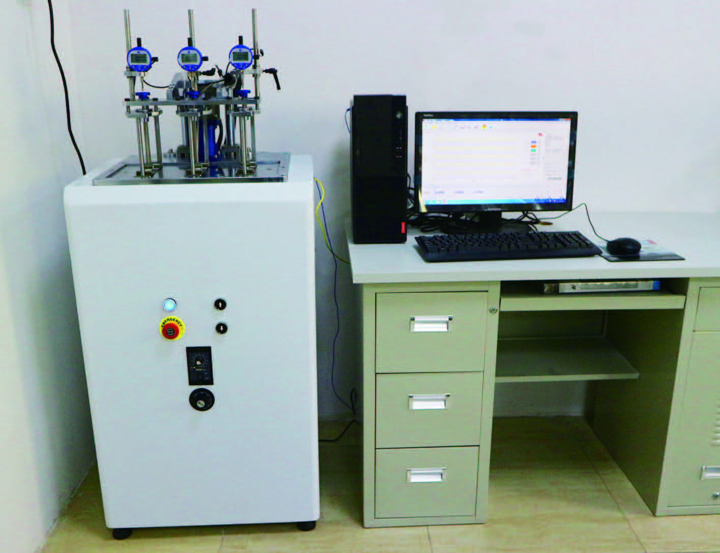
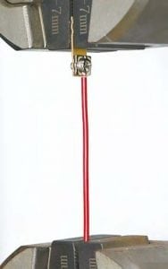
Vibration resistance is an important parameter for terminal blocks, especially if they are installed on trucks, trains or near an engine. In order to verify the effectiveness of the accidental loosening resistance of the terminals, these were subjected to cycles of 10 minutes of variable sinusoidal vibrational sequences covering the range of 1.7 Hz to 5 Hz with variable accelerations from 0.3 to 2.6 G for 48 hours, and the pull-out forces were again measured.
 |
Stranded conductor with crimped cable shoe, on a brass terminal with a notched steel square washer | ||||||||||
| Type | Torque (N.cm) | 0.5mm² | 0.75mm² | 1mm² | 1.5mm² | 2mm² | 2.5mm² | 4mm² | |||
| M3 screw (before vibrations) | 50 N.cm | 65 | 105 | 134 | 151 | 160 | 211 | ||||
| M3 screw (after vibrations) |
50 N.cm | 62 | 102 | 131 | 147 | 155 | 202 | ||||
| M3.5 screw (before vibrations) |
80 N.cm | 68 | 105 | 142 | 165 | 171 | 220 | ||||
| M3.5 screw (after vibrations) |
80 N.cm |
65 |
102 |
132 |
162 |
170 |
218 |
||||
| M4 screw (before vibrations) |
120 N.cm |
86 |
110 |
145 |
157 |
190 |
235 |
260 |
|||
| M4 screw (after vibrations) |
120 N.cm |
84 |
107 |
138 |
153 |
185 |
231 |
248 |
|||
| Minimum values requested by EN61210 | 20 | 30 | 35 | 40 | 45 | 50 | 60 | ||||
| Pull tests, made in our laboratory | |||||||||||
 |
 |
 |
|||||||||
| Pull test bench | Jaws detail | Terminal detail | |||||||||
| Vibration resistance tests, made in our laboratory | |||||||||||
 |
 |
||||||||||
| Vibration test equipment | Connection block during test | ||||||||||
Clearances and creepage distances
Creepage distances are measured by following the surface of the insulation, between two conductors of different polarity, or between a conductor and the ground. The minimum values of the creepage distances imposed by the standards depend, among other, on the operating voltage, the possible over-voltages on the network, and the specified application.
In the case of creepage measured on the surface of an insulator, the characteristics of the insulator used are important, because they will allow more or less easily the creation of electrical pathways, by forming conductive tracks. They are due to the superficial combustion by the electric current, in the presence of water of the plastic materials and the surface pollution of which the remaining carbon atoms become as many points of passage of the current. Plastics are therefore classified according to this feature.
It is called CTI (Comparative Tracking Index) in English and “Indice de Résistance au courant de Cheminement” (IRC) in French.
It is the maximum voltage, measured in volts, at which a material withstands 50 drops of contaminated water without tracking. Tracking is defined as the formation of conductive paths due to electrical stress, humidity, and contamination. The highest class of resistance to tracking currents is the 600V class, and therefore, this is the one that allows the smallest creepage distances. The ceramic and PA66 used in the devices in this catalog both have a CTI 600.
Clearances in air
The distances in the air (clearances), are the shortest distances measured in a direct line in the air between two conductors of a different voltage, or a conductor and the ground. They are representative of the path that would take an electric arc in the air during an overvoltage.
RoHS and REACH
RoHS : the materials used in the connection blocks comply with the European directive 2015/863 Annex II amending Directive 2011/65.
Certificates made by an accredited external laboratory available on request.
Reach: The materials used in the connection blocks comply with the REACH European Directives according to the June 2017 directive adding 173 substances SVHC (Substances of Very High Concern) from the list published by ECHA on 12 January 2017, applying to the directive Reach 1907/2006.
Certificates made by an accredited external laboratory available on request.
With or without halogens
According to the International Electrochemical Commission (IEC Standard 61249-2-21: Restricted use of halogen, intended for electronic circuits), to be classified in the “Halogen-free” category, a substance must contain less than 900 ppm of chlorine or bromine and contain less than 1,500 ppm of halogens. Halogen elements are any of the six non-metallic elements that constitute Group 17 (Group VIIa) of the periodic table. They are fluorine (F), chlorine (Cl), bromine (Br), iodine (I), and the rare and recently discovered astatine(At), and tennessine (Ts). The most common are chlorine and fluorine found in PVC and Teflon and its derivatives, and Bromine, used as a flame retardant additive in plastics. These products have the disadvantage of releasing toxic fumes when they catch fire. In addition to the risks to people, they also release corrosive gases harmful to electrical and electronic equipment. Among the flame retardants used in plastics, polychlorinated biphenyls (PCBs) and polybrominated biphenyls (PBBs) have an adverse effect on the environment and people due to their persistence, toxicity and ability to bioaccumulate.
Brominated flame retardants (BFRs) BFRs could form halogenated dioxins and furans when subjected to extreme thermal stress, which might occur during a fire.
PBBs and PBDEs (polybrominated diphenylethers), are now prohibited by the WEEE and RoHS Directives in Europe.
The PA66 plastic used in the connection blocks of this catalogue is halogen free, and complies with the existing standard in Europe.