Heat tracing applications
To reflect the maximum temperatures allowed by the insulating polymers, the powers of flexible heating cables are generally between 5 and 30W/meter, exceptionally 40W/m and 60W/m for self-regulating cables. These cables are coiled or laid longitudinally and in contact with the walls to heat. They are held in place by adhesives or metal strips. Classification for fire resistance is governed by EN 60332 Standard. Main recommendations for the use of flexible heating cables.
Connections : the heating cable ends must necessarily be connected to a non-heating section before entering the electrical control box.
Electrical protection :
All heating cables and ribbons must be installed with power protection complying with local regulations. For self regulating cables, the French Standard NFC 15-100 requires a circuit breaker or a GFCI with 30mA magnetic gauge to ensure the protection of persons.
Specific issues related to current peaks of self-adjusting cables :
These cables cause a significant current surge when they power up when cold. Refer to records of cable manufacturers to check the value.
Therefore, it is important to:
- To adjust the breaker rating based on that surge (values indicated by the standard CEI60898).
- Take into account this fact when selecting solid state relays. These surcharges are repetitive when the self-regulating cables are controlled by an external control system, we recommend over sizing SSRs, since repetition of these current peaks limits the lifetime of solid state relays (See above § for solid state relays).
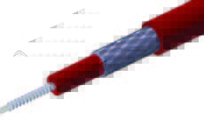
1. SERIES TECHNOLOGY
Bare series cable coiled on a fiberglass core
Bare series cable coiled on a fiberglss core with PVC, silicone or FEP (PTFE) insulation
Multi-strand series cable with PVC, silicone or FEP (PTFE) insulation
Series cable in metal tubing with magnesia insulation
Series cable with metal protection braiding
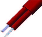
Series cable with non-heating return conductor
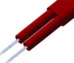
Series cable with two heating conductors
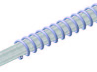
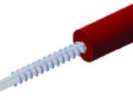
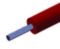
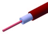
The heating cables are composed of a multi-strand single conductor, the strands can be straight or wound on a fiberglass core. The electrical insulation is typically PVC, Silicone, or FEP. The cables have a circular cross section and can accommodate a metal braid as a mechanical protection that can itself be coated with a flexible insulator. Each cable end is connected to the power supply. They are also available with two parallel conductors, one heating and one not-heating for return connection back, and also with two parallel heating conductors. They are defined by their metric resistance (Ohms / m) to be calculated according to the power and voltage, as well as technical limitations (composition of the strands, the maximum temperature withstood by insulation). Their length cannot be on-site adjusted. Models without protective braid are generally used in the refrigeration industry for defrosting cold room doors, defrost and evaporator flow, freeze protection of pipes, valves, water meters, etc. Models with protective braid are used for heat-tracing of great length pipes in petro chemistry for example.
Cable ends :
The cable ends must be fitted with a non-heating portion, cable or wires, which may be crimped or soldered, then coated with an insulator (silicone sleeve, heat shrink sleeve or molding: see pages 62-63)
Use heat shrink sleeves with caution for wire terminations if they are PVC, Polyolefin or flexible polymer-type TPR coated.
Temperature control :
This technology requires a temperature control system. A fixed setting thermostat, mostly a disc thermostat, can be molded at one end of the cable in the two parallel conductor versions (see pages 60-61)
2. CONSTANT WATTAGE PARALLEL TECHNOLOGY
Constant wattage cable protective braid
These flat ribbon-shaped cables are composed of two non-heating copper conductors delivering the 230V supply over the entire length of the ribbon.
The thermal effect is provided by the flow of current from one conductor to the other through a parallel mesh composed of resistive nickel-chromium wires alternately welded to one and the other of the two conductors. The electrical insulation is typically PVC, polyolefin, silicone, or FEP. The cables are flat section and may receive a mechanical protection by a metal braid which can itself be coated with a flexible insulator. These cords are connected to the power supply at one end, the other end to receive electrical insulation covering the cut.
They are defined by a watts per meter value. This technology allows the cutting of the heating cable to length, with an output directly proportional to the length.
It is adapted to maintain a medium heat, because its resistance does not vary as a function of temperature like for the selfregulating cables, and it is not restricted in temperature by the characteristics of the semiconductor resistive compound in selfregulating cables.
Cable ends :
The cable ends must be fitted with a non-heating portion, cable or wires, which may be crimped or soldered, then coated with an insulation (silicone sleeve, heat shrink sleeve or molding: see pages 103-104)
Use heat shrink sleeves with caution for wire terminations if they are PVC, Polyolefin or flexible polymer-type TPR coated.
Temperature control :
This technology requires a temperature control system. A fixed setting thermostat, mostly a disc thermostat, can be molded at one end of the cable in the two parallel conductor versions (see pages 93)
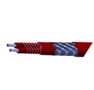
3. PARALLEL TECHNOLOGY, SELF-REGULATING TYPE
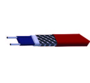
Self regulating cable with protective metal braid
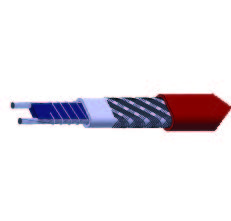
Limiting power cable with spacer between conductors
These flat ribbon-shaped cables are composed of two non-heating copper conductors (sometimes 3), delivering the power supply over the entire length.
The thermal effect is ensured by an extruded plastic polymer conductor, connecting the two copper conductors.
This polymer main thermal characteristic is the variation in its resistivity and thus its power per linear meter, depending on its temperature. This temperature is the result of its self-heating by Joule effect and its heat exchange outwardly by the wall on which it is placed, as well as the external temperature. The power reduction is in the region of 65% between 0 and 140 ° C (maximum temperature withstood by the polymer semiconductor).
This helps delivering the required power depending on environmental conditions.
This cable is also self-limiting and its power is greatly reduced when approaching the polymer temperature limit, thus avoiding destruction by overheating in the event of improper installation (overlapping or crossing wires, crossing insulation, etc). However, one must ensure that, in any case, the temperature of the fluid flowing in the pipe does not exceed the polymer critical temperature or it would cause its destruction.
The counterpart of this resistivity increase as a function of temperature is a resistivity decrease when the temperature drops. The starting power will be a function of ambient temperature. In the case of very cold environments, this causes large surges until the cable reaches its operating temperature. The startup power will be a function of ambient temperature. In the case of very cold environments, it causes large surges until the cable reaches its operating temperature.
A variant of this technology called power-limiting uses a coiled composite wire around two parallel conductors separated by a spacer of constant width. The characteristics of this wire allow a power limitation as its (…/…) power raises quite strongly with temperature.
The power reduction is in the region of 45% between 0 and 200 ° C. (Maximum operating temperature of the insulation).
This technology allows the cutting of the heating cable to length, with a maximum output directly proportional to the length. The electrical insulation is usually Polyolefin, Silicone, FEP or PFA. The cables have a flat cross-section and may receive a mechanical protection with metal braid that can itself be covered with a flexible insulation. These cords are connected to the power supply at one end, the other end of the cord to receive electrical insulation covering the cut. They are defined by a watts per meter value.
Cable ends :
- Solution 1: the cable ends can be made non-heating by cutting the semi conductive black plastic area between both conductors, over the whole connection length, which is usually long and tedious. After cutting, the wire non-heating part and plastic semiconductor cut is irregular and difficult to seal, even with soft silicone caps. Because of this irregular cross-section, the seal at the stuffing box packings cannot be guaranteed.
- Solution 2 (recommended by us): the cable ends must be fitted with a non-heating portion, cable or wires, which may be crimped or soldered, then coated with an insulation (silicone sleeve, heat shrink sleeve or molding: see pages 103-104).
Important note:
The semi conductive compound (carbon filled HDPP) used in these heating cables does not have a high temperature resistance. The use of heat-shrink sleeves on the ends and connections must be made with caution and avoid exceeding the compound destruction temperature.
Temperature control:
This technology does not systematically require a temperature control. However we recommend that these devices are equipped with temperature controls in order to control the temperature values requested by the processes.
4. CONNECTION ISSUES WITH HEATING CABLES
Overheating: their presence increases the room temperature. For example a box of volume 1500/2000cm 3 (current size of housing) will increase the ambient temperature of 20 ° C with just 5 watts of power dissipated inside.
This corresponds to 20 cm of 25 watts per meter heating cable, that to say a possible length needed to connect 3 heating wires in a distribution box. It is therefore important to avoid this type of assembly, especially when the box has an anti-freeze thermostat which measuring element is located in the housing itself and is therefore sensitive to its internal temperature.
The boxes in this catalog having antifreeze thermostats have been designed so that the temperature sensing element is outside the case. However, we recommend to connect the cables on a non-heating section prior to introduction into a control box to avoid internal overheating. We therefore propose a range of solutions for connecting to cope with all situations.
Power grid: in most cases, the on-site connection is made with no available grid. We have developed connection systems via screw terminals or crimp, which do not require power.
Cut-outs: they are often mounted on thermally insulated pipes and covered with a cover plate: we have focused on square and rectangular cutouts for the mountin stands. They are easier to achieve without power tools.
Connections are generally made outdoors: we developed watertight connection systems, achievable without electricity, with flexible caps and filling with liquid silicone which is room temperature vulcanizing. These caps have been designed to be easy to fill and use a simple system that allows them to maintain this position during the filling time and polymerization.
For economic mounting, when a heating system is available, we offer two types of retractable sheaths with intensive shrinkage, single wall for mounting where sealing is not necessary, and double wall, with in-wall fuse,for mounting where sealing is requested.
Removing the sheath and stripping are time-consuming: long and risky operations on oblong cables and in particular on these self-regulating cables. We therefore developed a complete range of wire strippers for these cables.