Float level switches technical introduction
1. Operation
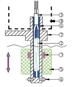
Operation diagram
| A1 : Vertical type | A2 : Horizontal type |
 |
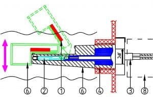 |
A float level switch is made of 8 main components
| 1: Magnet attached to the float (In reed switches devices) 2: Electrical contact (reed switch or micro-switch) 3: Electrical connection 4: Resin filling (for devices using a reed switch) |
5: Float 6: Float displacement limits 7: Level switch body, with its mounting system 8: Protection box (optional) |
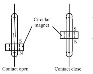
Magnet displacement and reed switch operation
| A1: Vertical type | A2: Horizontal type |
 |
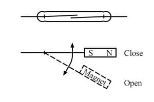 |
| In upright models, when the magnet, usually circular and surrounds the reed switch, is below or above the center of the reed switch, the contacts are opened. When the magnet is located at the center of the bulb, the contact is closed. | In horizontal models, a flat magnet (rectangular parallelepiped or disc) moves closer to the reed switch when the float turns on its axis when the magnet is close enough to the reed switch, the contact of the latter ‘s open. |
2. Description of the different parts
2.1 The magnet located inside the float (in devices using reed switch)
Selecting a magnet for a level switch application must take into account the characteristics of the liquid in which it will be immersed, of the temperature at which it will be subjected, of its corrosion resistance, of the magnetic field required to operate the switch and its distance to the reed switches. Sintered magnets are shock and vibration sensitive, “bonded” magnets have a low temperature resistance due to the resins used to agglomerate, and Neodymium –Iron-Boron magnets contain 60-75% iron (amount is dependent on grade) and are therefore prone to corrosion. Their price is extremely variable depending on the materials and manufacturing process, and therefore it is the sum of all these parameters that will decide if a type of magnet will be used rather than another in a specific application.
| Comparison of the characteristics of the main magnets types (Average values) |
| Material | Name | Grade | Br(KGs) | Hc(KOe) | Hci(KOe) | BH max(MGOe) | Tmax(°C)* |
| NdFeb** | Neodymium-Iron- Boron |
39H | 12.8 | 12.3 | 21 | 40 | 80 |
| NdFeb** | Neodymium-Iron- Boron |
B10N | 6.8 | 5.8 | 10.3 | 10 | 80 |
| SmCo | Samarium-Cobalt | SmCo26 | 10.5 | 9.2 | 10 | 26 | 300 |
| Alnico | Aluminum-Nickel- Cobalt |
Alnico 5 | 12.5 | 0.64 | 0.64 | 5.5 | 540 |
| Ceramic (Barium / Strontium) |
Ferrite | Y8T-Br | 2.2 | 1.8 | 3 | 1 | 280 |
| Ceramic (Barium / Strontium) |
Ferrite | Y30-Br | 3.8 | 2.4 | 2.5 | 3.5 | 280 |
| Ceramic (Barium / Strontium) |
Ferrite | Y30H-1 | 3.9 | 3.2 | 3.2 | 3.8 | 280 |
| Magnetic rubber*** | Ferrite flexible magnet | PRM-8 | 1.6 | 1.4 | 1.4 | 0.6 | 100 |
| ** Tmax is the maximum pratical temperature of use ** Rare earth magnets *** Flexible (Rubber) magnets are made by mixing ferrite or Neodymium magnet powders with synthetic or natural rubberbinders. Values given here are for ferrite |
Remanence (Br) is the flux density of a magnetic material in closed circuit, which remains after the removal of the magnetising field. Remanence is measured in Gauss, Tesla or mT. (1 Tesla = 10,000 Gauss)
Flux Density (B) is a measure of magnetic field strength of the magnet in an ‘open circuit’ condition. The actual flux density measured on the pole face of a magnet will depend on the material, the grade, the relationship of its pole area to its magnetic length and any additional pole pieces that create a further magnetic circuit. Flux density is measured in Gauss, Tesla or mT.
Coercive Force (Hc) is the strength of the demagnetizing field needed to reduce the flux density of the magnet to zero. Coercive force is measured in Oersted or kA/m.
Maximum Energy Product (BHmax) indicates the peak energy that a magnet can deliver when operating at a working point on the demagnetization curve. Maximum Energy Product is measured in Mega-Gauss-Oersted or kJm³.
2.2 The electrical contact system reed switch or a micro-switch.
A certain force is required to actuate the electrical contact device. It can range from a few tenths of grams for systems with reed contacts with a power rating of 10 to 20VA (0.5Amp), to several hundred grams for snap action micro-switches with a 16 or 20Amp electrical rating.
In general, the force required to operate an electrical contact increases with its electrical rating, and the power available on the detector depends on the float volume.
Most level switches in this catalog use reed switches because they are used for detection level in low voltage and low current electronic circuits. This makes possible to design compact devices.
Reed switches
Reed switches are small glass bulbs with a flexible reed strip contact with a breaking capacity of 10 to 50Va, which has the particularity to close in the presence of a magnetic field. These glass bulbs are sealed and filled with argon or under vacuum, therefore they are protected from oxidation.
Reed switches applications in level switches
| Suitable | Not suitable |
| Computer circuits | Small electrical motors , including small DC motors |
| Programmable logic controllers (PLC’s) circuits | Power contactor coils circuits (Unless protected by an arc suppression circuit) |
| Small relays | Solenoid valves (Unless protected by an arc suppression circuit) |
| Solid state relays(SSR) trigger circuits | Incandescent lamps |
Main models of reed switches used on float level switches maximum switching rating (resistive).
(Values given for a standard reed switch with magnetic sensivity of 25 Ampere Turns)
| Dimensions | Mini: L=14.5 mm x 2.2 mm dia. | Standard: L=20.5 mm x 2.7 mm max dia. | |||
| Power rating | 10VA (W)
Low voltage |
10VA (W)
High voltage |
10VA (W)
Low voltage |
40VA (W)
High voltage |
70W (W) High voltage |
| Max switching voltage AC | 110 | 400 | 110 | 250 | 250 |
| Max switching voltage DC | 150 | 400 | 180 | 200 | 200 |
| Max Amp 0-24V | 0.40 | 0.5 | 0.40 | 1 | 1 |
| Max Amp 30V | 0.33 | 0.33 | 0.33 | 1 | 1 |
| Max Amp 50V | 0.20 | 0.2 | 0.20 | 0.8 | 1 |
| Max Amp 80V | 0.13 | 0.15 | 0.13 | 0.5 | 0.9 |
| Max Amp 100V | 0.10 | 0.1 | 0.10 | 0.4 | 0.7 |
| Max Amp 110V | 0.09 | 0.09 | 0.09 | 0.36 | 0.64 |
| Max Amp 150V | 0.07* | 0.07 | 0.07* | 0.27 | 0.47 |
| Max Amp 180V | N/A | 0.06 | 0.06* | 0.22 | 0.39 |
| Max Amp 230V | N/A | 0.04 | N/A | 0.17 | 0.30 |
* DC loads only
Reed switches contact protection
Switching no load or loads where the voltage is less that 5 Volts @ 10 mA or less, the contacts undergo little or no wear and life times in excess of billions of operations are expected. In the 10 Volt range, higher contact wear will take place. Switching 10 Volts @ 10 mA, life times of 50 million to 200 million operations can be expected.
When switching inductive loads such as relays, solenoids and transformers, reed switch contacts require protection in order to insure long, dependable life. When current is interrupted, the inductance or electrical inertia of the load generates a large high frequency voltage, which appears across the switch contacts. If the voltage is large enough, it can break down the medium in the
gap between them, making a conductive path. This phenomenon is called arcing. Arcing can cause the contacts to burn, weld together or stick. The purpose of protection circuits is to prevent arcing, by shorting this voltage through an alternate path.
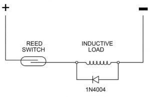
| DC load contact protection circuit with diode | AC load contact protection circuit with R/C circuit |
 |
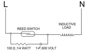 |
| A 1N4004 diode is connected cathode-to-positive .The diode does not conduct when the load is energized, but conducts and shorts out the peak transient generated voltage when the switch opens. A resistor can be added in serial with the diode. | A resistor (R) and capacitor (C) are connected in parallel with the switch. The capacitor has high impedance at 50/ 60 hertz, and is essentially a short circuit to high frequencies of generated voltages. Capacitor value: C = I²/10 Resistor value (E= power supply voltage): R = E / (10.I(1+50 / E )) |
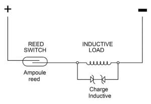
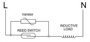
| DC load protection contact with Back to Back Zener diode | AC load protection contact with Varistor |
 |
 |
| The peak transient voltage that occurs when the switch opens is decreased to a value equal to the back to back Zener diode voltage. The Zener diode should be sized for a voltage somewhat higher than the circuit source voltage |
The varistor resistance decrease sharply when voltage reaches its trigger value, and shorts out the peak transient generated voltage when the switch opens. Varistor should be sized for a voltage somewhat higher than the circuit source voltage |
Snap action switches (Micro-switches)
On snap action switches, contact opening speed is around 1m per second.
The contacts spacing reach the distance to extinguish the arcing in less than 1/1000 sec. Therefore there is no radio interference, and the contact does not deteriorate. Mechanically, this type of contact, also called “ energy storing contact” is much more complicated, expensive, and does not allow such a great control than reed switches.
The snap action microswitch is particularly suitable for devices operating at 240 or 400 V and when high electrical rating is required.
Microswitches uses in level switches
| Disadvantages | Advantages |
| Higher price than reed switch | High electrical rating, up to 30A 110VAC to 230VAC |
| Microswitches have a higher operating force, so they need float with bigger volume | SPNC, SPNO or change over contacts |
| Large differential travel on the switch, providing important distance in high and low switching levels | Snap action contacts do not generate EMC |
Micro-switch contact material and contact plating in level switches applications
The contact of a micro-switch wears by micro vaporization at each open and close cycle. This wear is proportional to the strength and duration of the electric arc.
The most common contact material is pure or alloyed silver. Its thermal conductivity quickly evacuates the temperature peak occurring during these cycles.
Its very good electrical conductivity provides very low contact resistance, usually less than 3 milli-ohms.
However it oxidizes and is gradually covered with a thin layer of silver oxide, which is not electrically conductive.
This layer is easily vaporized when the switch is used in common household voltages (240V, 300V). However, when used in low voltage (less than 12V) and very low currents (a few milli-amps), and less than 800mW, the contact opening arc is no longer sufficient to vaporize the silver oxide layer. The solution is to plate the contact with a thin layer of gold (said gold flash) 3 to 5 microns thick, to ensure its protection, especially under conditions of high humidity to which are generally subject level switches.
Comparison of contact materials and plating
| Silver and silver alloys | Gold plated silver |
| High electrical rating, mandatory use for electrical rating higher than 1A 250VAC |
Cannot be used on voltages lower than 0.1 millivolt, because the contact resistance is too high |
| Oxidize and the contact resistance increases with time if they are used to cut electrical rating less than 20V and 100 mA | The use on voltages higher than 30V and / or with currents above 100 mA causes vaporization of the gold flash protection. Then contact behaves like a standard silver contact |
| Cannot be used in oxidizing atmosphere | If the load is less than 30 mV and 10 mA, there is no change in the contact resistance and electrical life becomes very important (except atmospheric contamination by hydrocarbon) |
2.3 Electrical wiring
For reed switches systems, the most common electrical connection is by wires or cable. Given the low electrical rating of reed switches, conductor cross section is generally less than or equal to 0.5 mm ². If there is no thermal stress or environmental conditions, wires and cables are PVC insulated. Silicone insulation, FEP and Teflon are not recommended because they do not provide hermetic sealing with resin filling and may let in water or moisture inside the product.
Tabs or connector outputs are recommended for large quantities.
2.4 Resin filling (For reed switch types)
The resin filling provides two functions
- Mechanically securing the reed in the body, and provide its resistance to tearing (Standards impose a tearing resistance equal to or greater than 10N)
- Main electrical insulation of the electrical contact and wiring. This requires a UL94-VO resin. In some customer applications the insulation class I is insufficient, and the contact system must receive and additional insulation to comply to the requirements of insulation class II
2.5 Float
The main requirements of floats are to have a lower density than the liquid in which they must float, to withstand the pressure and temperature of the medium in which they are located, and remain sealed. The vertical float level switches may receive several floats on the same stem, each float actuating an independent switch.
There are three float manufacturing technologies:
– Hollow metal floats
– Hollow plastic floats,
– Plastic foam floats.
All three models can be interchangeable on the same axis.
In some vertical models using a reed switch, a wise magnet position in the float can allow to reverse the contact open and close positions by simple reverse of the float.
On horizontal reed switch model, it is the 180 ° rotation of the entire device which reverses the contact operation
Advantages and disadvantages of the 3 types of floats
Buoyancy:
In the hollow floats, the wall thickness will be optimized to give the best buoyancy to withstand the maximum pressure and temperature at
which it can be subjected during normal operation.
The maximum pressure limit can vary from 0.05 MPa to 1 MPa depending on the model and thicknesses.
Foam floats need to carefully monitor the foam density to achieve constant and reliable buoyancy. The foams are closed-cell type, with a slight skin to prevent the ingress of liquid between foam bubbles.
Temperature resistance:
Compared to metal floats, floats plastic have the advantage of better buoyancy and a lower price, but the disadvantage of a lower pressure and temperature resistance. The chemical resistance of plastics varies greatly depending on the materials used.
Temperature limits of plastic floats are generally below 85 ° C (Permanent temperature) . It is possible under certain conditions to use materials that offer higher heat resistance (up to 125 ° C or more).
Chemical resistance:
The material used must be compatible with the nature of the fluid or liquid with which the float is in contact. In addition, it should not harden or crack over time. Gas or liquid in contact with the float may have a corrosive or destructive short, medium or long term on it, eg ozone, chlorine and its compounds, bromine and its compounds, solvents, hydrocarbons etc.
Contact with drinking water:
In some applications, when the float is in contact with drinking water, health standards are added, which regulate the chemical composition. The highest standards known, that are used as a normative reference in many countries are those issued by the FDA (Food and Drug Administration, USA) and the WRC (water research council, GB). Stainless steel floats are most appropriate to meet the requirements for drinking water. In the case of plastic floats, these standards provide particularly maximum permissible surface in contact with water and the maximum temperature at which the plastic may be exposed without harmful compounds are released into the water.
Contact with strongly calcareous waters:
When the floats are used in waters heavily loaded with calcium salts, it may deposit on the float and the body of the level sensor. This deposit has two consequences: a heavier float, which can cause it to sunk and reduced dimensional gaps between the float and the body, that may result into a mechanical lock.
There is no definitive solution to address these problems. It is possible to delay the lock by using bigger floats (which therefore produce a larger force), and increase the mechanical clearance between the float and the body.
Silicone oil based non sticking products can also be sprayed lightly on the parts, but their compatibility with the materials of the float and the body and operating conditions must be carefully checked.
Contact with viscous fluids:
We do not recommend using level switches with moving parts (so of course all systems float) on fluid with a dynamic viscosity of less than 0.5×10⁻⁴ Pa.s or above 10-2 Pa.s
Usual liquids dynamic viscosity (Pa.s)
| Gasoline | Methanol | Water | Sea water | Ethanol | Kerozene | Blood (37°C) | Ethyleneglycol | Sulfuric acid | Motor oil SAE 10 (20°C) | Olive oil | Motor oil SAE 40 (20°C) | Honey | Molten chocolate |
| 2.92×10-⁴ | 5.98×10-⁴ | 1×10-³ | 1.07×10-³ | 1.2×10-³ | 1.92×10-³ | 3×10-³ | 2.14×10-² | 2.42×10-² | 6.5×10-² | 8.1×10-² | 0.32 | 2~10 | 45~130 |
Magnetic particles:
Level switches are based on a magnet housed inside the float, so liquids containing magnetic particles such as iron filings must be avoided, because these particles will accumulate on the magnet.
Waves and stirring at the liquid surface:
If the surface of the liquid is agitated by waves, the float will move quickly by following the oscillations of the surface and thus operate the switch to the frequency of these oscillations. There are two solutions to mitigate these shortcomings:
– Install a timer relay on the contact output circuit
– Install an anti-waves shell around the float. This shell is a small box with small holes that will damp the oscillations. The smaller are the holes, the more important is the gap between the liquid level inside and outside the, so one’s must find the right balance between removing waves and rapid control level.
2.6 Float up and down mechanical stops
The mechanical displacement of the float must be limited to remain within the limits of the magnet position detection by the reed switch. There are on the market float level sensors with clips allowing two select two possible relative positions of the float, a position giving a normally closed contact and one normally open contact.
JPC floats are designed for these two positions are possible by simply inverting the float.
2.7 Mechanism body and mounting system
Choice of material:
The body of the mechanism provides several functions:
– Device protection against electric shock, water ingress, pressure value, and chemicals.
This body must meet the same requirements as the float, but are added special features due to its electrical protection function.
Plastics used by JPC for the body are always UL94-VO rated
– The float guidance: guiding the float requires the use of plastics that do not wear out easily, with a low friction coefficient
– The level switch mounting:
This mounting can be secured by NPT or BSPT (Tapered) threads, or BSPP cylindrical threads or metric threads. Tapered threads require sealing on the threads, and the cylindrical threads require sealing by a flat gasket.
In general the vertical flow switches are inserted from the inside of the tank, and secured with an outside nut and gasket, and horizontal flow switches are mounted from the outside of the tank on a female fitting.
In large quantities applications of vertical level switches, preference is given to a side bracket, which is better suited for screwdriver assembly.
Depending on the application level sensors will be mounted at the bottom, side or top of tanks. Mounting solution design can be adapted to these requirements.
– Cover: an optional cover can be attached either by a central tapping or by screws and gasket on the body of the level switch.
2.8 Protection housing
The protection housing can have several functions:
– Ingress protection against attacks from the outside environment (rain, dust, shock)
– Protection against the conditions in which the product will be installed in its application.
In most cases, level switches will be integrated by an OEM into a machine or equipment. Then it is this machine or equipment that will ensure protection against water, dust, shock and other contaminants.
– Protection against usual external environment: These are usually plastic housings providing an IPxx (Protection against the
penetration of water and dust, EN 60529a degree of protection) and an IKxx (Protection against shock, EN 50102).
– Protection against gas and dust explosive atmospheres: JPC level switches are not designed for use in these environments and therefore do not meet the applicable standards in this field of application
3. Values and definitions
Level differential
The level differential (also known as “differential” or “hysteresis”) is the difference between the position of the float where
it actuates the electrical contact by a level variation, and the position it goes back to its original state when the level change is reversed. A general rule is that the level differential increases with the nominal electrical rating. A level switch with a small electrical rating will generally have a small level differential
Vocabulary
Level switch definition: A level switch is a device which detects the exceeding of a predetermined value of the level of a liquid. The information is made in the form of an electrical contact opening or closing a circuit
Synonyms and similar words:
Level sensor, level switch, level control, level sensor
Level switch selection parameters
Selecting a level switch must take in consideration:
– The temperature of the liquid
– The viscosity of the liquid
– Pressure at which it shall be subjected,
– The type of liquid,
– The type of contact (NO, NC, SPDT)
– Electrical rating (voltage, current)
– The environment (protection against water, dust, shock)
– The position on the tank