Cables and accessories connection methods with silicone filling
1. Sensors and accessories to be mounted in ISO M20x1.5 threads (type G sleeves)

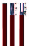
1. Cut the lead wires of the accessory to 13mm, strip the conductors of 6 to 8mm, twist them and insert the stripped portion into each tubular connector.

2. Crimp the tubular connectors with the hexagonal crimping pliers. The center of each crimp must be at around 4mm from the edge.
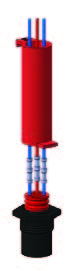
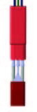
3. Insert the wires into the silicone sleeve. Make sure that the conductors are in their dedicated holes. Slip the sleeve on the wires to the stop after the locking grooves by using the bottom flap. The conductors are then entirely set in their places.
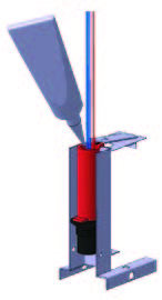
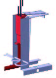
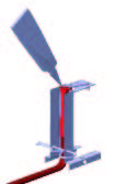
4. Position the assembly on the filling support and lock it with the upper flap of the sleeve, which has a flange for this purpose. Fill with liquid silicone. It is possible to cut the insertion and filling flaps after polymerization.
2. Heating cables on non heating ends (Sleeves C and D)

1. Cut the ribbon to the requested length.
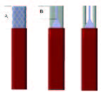
2. Remove the outer protective jacket of 18mm (if any)
• If the cable has a metal braid, unbraid it (without cutting any wire) with the tip of a pen or a small metal rod with a rounded end, then group it and twist it in a continuous beam
• Remove the second protection jacket of 10 mm. minimum
3. Strip the two conductors of 6 to 8 mm, twist them and insert the exposed portion in each tubular connector.
In the case of cable with metallic braid, insert the twist which is cut to the same length than the drivers in a tubular connector.
![]()
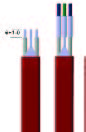
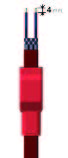
4. Crimp the tubular connectors with the hexagonal crimp pliers. The center of each crimp should be around 4 mm from the edge. Crimp one side of the heating cable and the other side on the non-heating conductors. If the cable has a metal braid, this braid is the ground conductor.
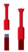
5. Insert the wires into the smallest part of the silicone sleeve. Ensure that the conductors are inserted in their dedicated holes. The central hole is for the ground conductor.
6. Slide the sleeve over thewires to the stop, using the flat flap located on the heating element side. The tubular conductors are then fully inserted in their
7. Position the assembly on the filling support and lock it with the flap which has a flange.
8. Fill with liquid silicone in the largest neck (connection wires outlet). It is possible to cut the insertion and filling flaps after polymerization.
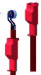
3. Heating cable end (type E sleeves)
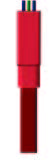
1. Cut the ribbon to the requested length. Remove 10 to 12 mm of the metal protective braid (if any) in order to ensure a good grip to the silicone. Make sure that none of the wires of this braid exceeds the cut length, which could cause short circuits
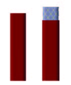
2. Insert the silicone sleeve on the ribbon end to the stop by pulling the bottom flap.
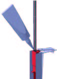
3. Position the assembly on the filling support and lock it with the upper flap of the sleeve, which has a flange for this purpose. Fill with liquid silicone in the upper shell-hole.
4. It is possible to cut the insertion and filling flaps after polymerization if necessary.
4. Disc thermostat assembly (anti-freeze ofr other set points) on the end of line (type A sleeves)
1. Cut the ribbon to the requested length. Remove the first protective jacket. Remove 15 to 16mm of the second protective jacket and the metal braid to (if any).
2. Position the silicone sleeve on the heating ribbon . Strip 4mm on both conductors.
3. Solder both wires on the disc thermostat terminals. Then slide the sleeve until the thermostat goes to three stop in its place.
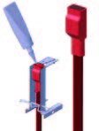
4. Position the assembly on the filling support and lock it with the upper flap of the sleeve, which has a flange for this purpose. Fill with liquid silicone in the upper shell-hole. It is possible to cut the insertion and filling flaps after polymerization if necessary.
5. Connection methods for cables accessories with heat shrinkable sleeve
![]()
1. Strip the conductors of 6 to 8 mm, twist them and insert the stripped portion into each tubular connector. If both parts to connect are multi conductor cables, removing the protective jacket must be done on the appropriate length in order to properly slide a heat shrinkable sleeve. If the cable has a metal braid, unbraid it (without cutting any wire) with the tip of a pen or a small metal rod with a rounded end, then group it and twist it in a continuous beam. The conductors and the twisted braid must be the same lengths.
2. Crimp the tubular connectors with the hexagonal crimp pliers. If the cable has a metal braid, crimp a braid end in a tubular connector.
The center of each crimp should be around 4 mm from the edge. Then slide a insulation sleeve on each conductor having a crimped tubular connector. Insert the other element conductors into the second end of the tubular connectors. Crimp. The center of each crimp should be around 4 mm from the edge.
![]()
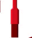
3. Slide the shrinkable sleeves to a center position on the tubular connectors. Shrink the sleeves one after another with heat gun or a heat source. Do not exceed the shrinking temperature, as this may destroy the sheath or cause cracks.
![]()
4. After checking the integrity of the shrink sleeves, put a heat shrinkable sheath around the cable, on the sleeves, and shrink the same way.
Similarly, it is possible to seal the opposite end as follows: If the ribbon has a protective metal braid, remove a few millimeters of its outer jacket to improve the shrinkable sleeve grip. Ensure that no wire of this braid could be in contact with