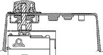
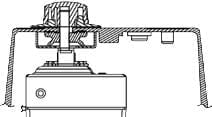
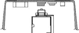
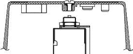
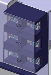
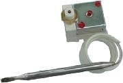
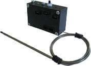
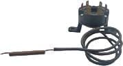
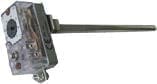
JPC Design concept of the Y1 types aluminum enclosures
1. The range design concept and main features
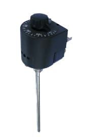
Y1 range includes a wide range of thermostats in IP65* metal housing with high mechanical resistance (IK10** except models with external knob), intended for commercial or industrial applications covering ranges from -35 °C to +760 °C.
Technical details are the result of more than 50 years of experience and field comments.
*IP65= totally protected against dust and protected against low pressure water jets from all directions
**IK10= resistant to the impact of a 5kg weight dropped from 40 cm(=20 Joules)
2. Compatible thermostats
 |
 |
   |
   |
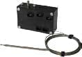
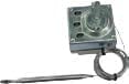
| Liquid expansion thermostats, ambient or antifreeze |
Electronic thermostats, ambient or antifreeze | Temperature control, liquid expansion thermostats, single pole and 3 poles | Fixed setting, manual-reset,liquid expansion thermostats, single pole double pole or 3 poles |
 |
  |
  |
 |
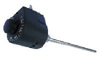
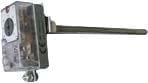
| Adjustable manual-reset, liquid expansion thermostats, single pole | Combination of temperature control + manual reset liquid expansion thermostat, single pole | Bimetal expansion rod temperature control thermostats, single pole and double pole |
Bimetal expansion rod manual reset thermostats, single pole and double pole |
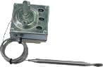
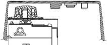
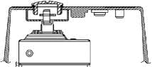
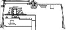
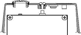
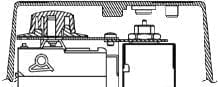
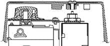
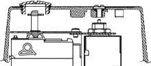
3. Set point adjustments on control thermostat (IP65)
3.1 Control thermostats (IP65)
 |
 |
 |
 |
 |
| Inside adjustment | Screw driver adjustment, under screwed cap | Inside adjustment by knob, access by window | Outside knob adjustment, bottom mounted thermostat (not available on all models) | Outside knob adjustment, thermostat mounted on cover (3 pole and electronic control) |
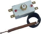
3.2 Manual reset thermostats: access to reset button (IP65)
 |
 |
 |
| Fixed setting limiter, inside manual reset | Fixed setting limiter, outside manual reset with a tool | adjustable setting limiter, outside set point adjustment under screwed cap,outside manual reset with a tool |
3.3 Combination of control and manual reset thermostats: access to set point adjustment and to reset button (IP65)
 |
 |
 |
 |
 |
| Control thermostat with inside set point adjustment, manual reset thermostat with inside access |
Control thermostat with inside set point adjustment, manual reset thermostat with outside access with a tool |
Control thermostat with outside set point adjustment under screwed cap, manual reset thermostat with outside access with a tool |
Control thermostat with outside set point adjustment under screwed window, manual reset thermostat with outside access with a tool |
Control thermostat with outside set point adjustment by knob, manual reset thermostat with outside access with a tool |
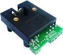
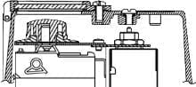
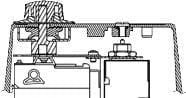
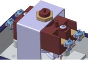
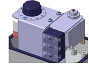
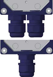
4. Electrical connections and cable outputs
 |
 |
 |
 |
 |
 |
|
The internal grounding |
Metallic adjustment |
The electrical |
The electrical connection of 2 and 3 pole limiters, 3 pole thermostats, bimetal rod thermostats and electronic control is made directly to the screw terminals on the device |
Thermostats are |
Output made by cable gland ISO M16 PA66, IP68, for cable dia. 5 to |
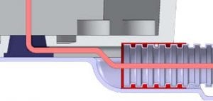
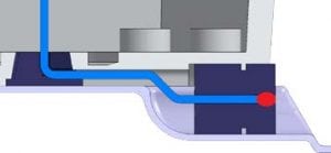
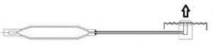
5. Sensors and temperature measurement probes
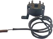
- Electronic ambient measurement sensor are protected by a silicone boot.
- The outputs of the temperature sensors of electronic models are protected by a flexible stainless steel sheath.
- The outputs by capillary are protected by a flexible stainless steel sheath terminated by a ferrule for pocket mounting, or by a flexible silicone termination for measurements without pocket.
- Rod thermostat outputs are sealed with gasket.
- Rod thermostats exist with bimetallic expansion or liquid expansion measuring system
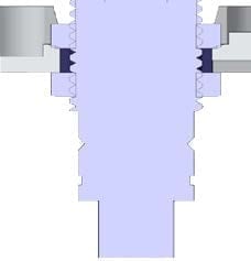
- The pocket mounting system is identical across the Y1 range (see Y1 range accessories)
- Rods are made of 304L stainless steel
 |
 |
 |
| Capillary output | Electronic ambient measurement sensors | Rod output |
 |
 |
 |
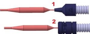
| Silicone boot (1) or ferrule (2) termination for capillary output |
Rod output pocket mounting system | Pipe mounting bracket model (1: SS304 band, 2: Hose clamps, 3: Tie wraps) |
6. Temperature measurements principles
| Bimetallic expansion measurement: Used on some rod models. | Liquid expansion measurement: Used on the ambient control thermostats, bulb and capillary thermostats, pipe mounting thermostats and on some rod thermostat models |
 |
 |
| Advantages: – Fast response time, – No risk of leakage measurement – Simple mechanical – Insensitive to ambient temperature variations on the head – Measurement of the average temperature over the entire length of the rod – Good resistance to overheating Disadvantages: – Relatively sensitive to vibrations, – Rigid rod cannot be bent or folded – Length cannot be changed |
Advantages: – Available in different capillary lengths – Allows to make rod thermostats with short or very long probes – Flexibility of the capillary – Quite insensitive to vibrations Disadvantages: – Sensitive to ambient temperature variations on the body – The risk of leakage on bulb or capillary requires in some applications to use failsafe limiters – The overheating of the bulb beyond the permissible values may cause deterioration of the diastat |
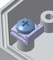
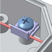
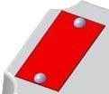
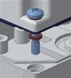
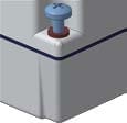
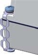
7. Fasteners and identification
| Unalterable identification plate, riveted and customizable. | Stainless steel captive cover screws | Anti-galvanic corrosion insulating washers under the screw heads |
Miniature chain provides non-detachable cover,avoiding to drop it during electrical connection or maintenance. (Comply to EN60335-26-1) |
 |
 |
 |
 |
8. Aluminum enclosure material
| Material and standards | Si | Cu | Mg | Zn | Mn | Fe | Ni | Sn | Al |
| ADC12 (JIS H5302:2000) | 9.6-12.0 | 1.5-3.5 | <0.3 | <1.0 | <0.5 | 0.6-0.9 | <0.5 | <0.2 | rest |
Surface protection
Enclosure are sand blasted and epoxy painted, oven cured, color grey RAL7035 (Other colors : MOQ apply)
Regulations
Non-self resetting protective device: It requires the use of a tool or removal of a cover to reset it. (EN60335-1, §30-1)
Adjustable limiter: Appliances provided with controls or switching devices are tested with these controls or devices adjusted to their most unfavourable setting, if the setting can
be altered by the user. If the adjusting means of the control is accessible without the aid of a tool, this sub-clause applies whether the setting can be altered by hand or with the aid of a tool. If the adjusting means is not accessible without the aid of a tool and if the setting is not intended to be altered by the user, this sub-clause does not apply.
Adequate sealing is regarded as preventing alteration of the setting by the user (EN60335-1, §5-6).
Definitions of temperature control devices
Thermostat: Temperature-sensing device, the operating temperature of which may be either fixed or adjustable and which during normal operation keeps the temperature of the controlled part between certain limits by automatically opening and closing a circuit (EN60335-1§3.7.1)
Temperature limiter: Temperature-sensing device, the operating temperature of which may be either fixed or adjustable and which during normal operation operates by opening or closing a circuit when the temperature of the controlled part reaches a predetermined value. It does not make the reverse operation during the normal duty cycle of the appliance. It may or may not require manual resetting. (EN60335-1§3.7.2)
Thermal cut-out: Device which during abnormal operation limits the temperature of the controlled part by automatically opening the circuit, or by reducing the current, and is constructed so that its setting cannot be altered by the user (EN60335-1§3.7.3)
Self-resetting thermal cut-out: Thermal cut-out that automatically restores the current after the relevant part of the appliance has cooled down sufficiently (EN60335-1§3.7.4)
Non-self-resetting thermal cut-out: Thermal cut-out that requires a manual operation for resetting, or replacement of a part, in order to restore the current. (EN60335-1§3.7.5).
Protective device: Device, the operation of which prevents a hazardous situation under abnormal operation conditions (EN60335-1§3.7.6)
Thermal link: Thermal cut-out which operates only once and requires partial or complete replacement (EN60335-1§3.7.7)
9. Description of thermostats used in Y1 enclosures
(For more information, consult the Introduction to Thermostats Technology in our catalogue N°1)
| 8G | KR | 8C | SR, VR | 1R, 1B |
 |
 |
 |
 |
 |
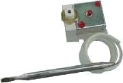
| Bulb and capillary control thermostat, liquid expansion, appliance type, Single Pole Double Throw contact, 16A 250V For Y1 series, they are used in the following versions: – wall mounting models for ambient temperature control, – bulb and capillary models, – rod models – tube mount models. Temperature ranges available from -35°C to 300°C. Electrical life time: 100.000 cycles |
Bulb and capillary control thermostat, liquid expansion, commercial and industrial type, Single Pole Double Throw contact, 15A 250V/400V For Y1 series, they are used in the following versions: – wall mounting models for ambient temperature control, – bulb and capillary models, – rod models. Temperature ranges available from -25°C to 760°C. Electrical life time: 500.000 cycles. They withstand -50°C. Do not fit combined versions with a safety thermostat. (also available in low differential version: KU) |
Bulb and capillary control thermostats, liquid expansion, appliance type, three poles, Normally Closed contacts, 16A 250V, 10A 400V For Y1 series, they are used in the following versions: – wall mounting models for ambient temperature control, – bulb and capillary models, – rod models – tube mount models. Temperature ranges available from -35°C to 300°C. Electrical life time: 100.000 cycles. Do not fit combined versions with a safety thermostat. |
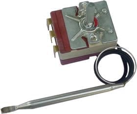
Invar Rod thermostats for temperature control, commercial and industrial type, Single Pole Double Throw contact, 15A 250V/400V For Y1 series, they are used in the following versions: – rod models. Temperature ranges available from 0°C to 150°C for S series and up to 300°C for V series. Electrical life time: 500.000 cycles. Do not fit combined versions with a safety thermostat. (also available in low differential versions: SU, VU) |
Invar Rod thermostats for temperature control, commercial and industrial type, Single Pole Double Throw contact (1R) or Double Pole Normally Closed (1B), 15A 250V/400V For Y1 series, they are used in the following versions: – rod models. Temperature ranges available from -10°C to 165°C. Electrical life time: 100.000 cycles. Do not fit combined versions with a safety thermostat. (also available in low differential versions: 1U, 1C) |
| 8L | KX | 8X | 82 | 1X, 1E |
 |
 |
 |
 |
 |
| Bulb and capillary cut-outs, fixed setting, fail safe, vapor pressure (also called boiling), appliance type, Normally Closed contact, 15A 250V For Y1 series, they are used in the following versions: – wall mounting models with manual reset (unusual version), – bulb and capillary models, – rod models, – tube mount models. Temperature set points available between +70°C to +300°C. Electrical life time: 300 cycles. |
Bulb and capillary cut-outs, with adjustable set point, liquid expansion, commercial and industrialtype, Single Pole Normally Closed contact, 15A 250V/400V For Y1 series, they are used in the following versions: – wall mounting models with ambient temperature control, – bulb and capillary models, – rod models. They withstand -50°C. Do not fit combined versions with a control thermostat. Temperature ranges available between -25°C to 760°C. Electrical life time: 100.000 cycles. |
Bulb and capillary cut-outs,fixed setting, vapor pressure (also called boiling), appliance type, Double Pole Normally Closed contacts, 20A 250V For Y1 series, they are used in the following versions: – wall mounting models with manuel reset (unusual version), – bulb and capillary models, – rod models, – tube mount models. Do not fit combined versions with a control thermostat. Temperature set points available between +70°C to +170°C. Electrical life time: 300 cycles. |
Bulb and capillary cut-out,fixed setting, vapor pressure (also called boiling), commercial type, Three Pole Normally Closed contacts, 25A 250V, 16A 400V, double break contacts For Y1 series, they are used in the following versions: – wall mounting models with manual reset (unusual version), – bulb and capillary models, – rod models, – tube mount models. Do not fit combined versions with a control thermostat. Temperature set points available between +70°C to +170°C. Electrical life time: 300 cycles (250V), 1000 cycles (400V) . |
Invar Rod thermostats with manual reset, commercial and industrial type, adjustable or fixed setting, Single Pole Double Throw (1X) or Double Pole Normally Closed (1E), 15A 250V/400V For Y1 series, they are used in the following versions: – rod models. Do not fit combined versions with a control thermostat. Temperature ranges available from -10°C to 165°C. Electrical life time: 1000 cycles. |
10. Comparative features of the Y1 range models
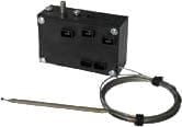
10.1 Ambiance control thermostats, antifreeze thermostats
| Type Y1 | Type interne | Sensing element | Set point adjustment access | Action type |
Contacts |
Limits of possible temperature ranges | ||||||
| Liquid expansion | Electronic sensor | Inside | Cap | Window | Outside knob | Control | Manual reset | Combination control + reset | ||||
| Y1A | KR KU | -25+70°C | ||||||||||
| Y1A | 8G* | -35+40°C | ||||||||||
| Y1B | KR KU | -25+70°C | ||||||||||
| Y1B | 8G* | -35+40°C | ||||||||||
| Y1C | KR KU | -25+70°C | ||||||||||
| Y1C | 8G* | -35+40°C | ||||||||||
| Y1C | 8C | -35+40°C | ||||||||||
| Y1D | 2PE2N | -35+40°C | ||||||||||
| Y1E | 2PE2N | -35+40°C | ||||||||||
| Y1F | 2PE2N | -35+40°C | ||||||||||
* This range can also be done with manual reset models or combined control thermostat + manual reset (Unusual options). Contact us for references.
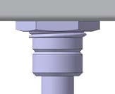
10.2 Pipe surface mounting thermostats (liquid expansion sensor)
| TYpe Y1 | Type inside | Set point adjustment access | Manual reset access | Action | Contacts | Limits of possible temperature ranges | ||||||
| Inside | Cap | Window | Outside knob | Inside | Outside access under screwed cap | Control | Manual reset | Combination control + reset | ||||
| Y10 | KR, KU | 0+120°C | ||||||||||
| Y10 | 8G | 4+110°C | ||||||||||
| Y11 | KR, KU | 0+120°C | ||||||||||
| Y11 | 8G | 4+110°C | ||||||||||
| Y12 | KR, KU | 0+120°C | ||||||||||
| Y12 | 8G | 4+110°C | ||||||||||
| Y12 | 8C | 4+120°C | ||||||||||
| Y13 | 8L* | 30-120°C | ||||||||||
| Y13 | 8X* | Fail safe |
70-120°C | |||||||||
| Y13 | 82* | Fail safe |
70-120°C | |||||||||
| Y14 | KXA*, KXF | 0+120 | ||||||||||
| Y15 | KXA* | 0+120 | ||||||||||
| Y16 | 8G+8L* | 4+120°C | ||||||||||
| Y17 | 8G+8L* | 4+120°C | ||||||||||
* This range can also be done with internal manual reset (Unusual options). Contact us for references.
10.3 Bulb and capillary thermostats (Liquid expansion measurement)
|
Type Y1 |
Type inside |
Set point adjustment access | Manual reset access | Action type |
Contacts |
Limits of possible temperature ranges |
||||||
| Inside | Screwed cap | Window | Outside knob | Inside* | Cap | Control | Manual reset | Combination control + reset | ||||
|
Y1G |
KR KU |
-25+760°C |
||||||||||
|
Y1G |
8G |
-35+300°C |
||||||||||
|
Y1H |
KR KU |
-25+760°C |
||||||||||
|
Y1H |
8G |
-35+300°C |
||||||||||
|
Y1I |
KR KU |
-25+760°C |
||||||||||
|
Y1I |
8G |
-35+300°C |
||||||||||
|
Y1J |
KR KU |
-25+760°C |
||||||||||
|
Y1J |
8G |
-35+300°C |
||||||||||
|
Y1J |
8C |
-35+300°C |
||||||||||
|
Y1K |
8L |
Fail safe |
60-300°C |
|||||||||
|
Y1K |
8X |
60-170°C |
||||||||||
|
Y1K |
82 |
Fail safe |
60-170°C |
|||||||||
|
Y1L |
8L |
Fail safe |
60-300°C |
|||||||||
|
Y1L |
8X |
Fail safe |
60-170°C |
|||||||||
|
Y1L |
82 |
Fail safe |
60-170°C |
|||||||||
| Y1M | KXA | -25+760 | ||||||||||
| Y1N | KXA | -25+760 | ||||||||||
| Y1O | KXA | -25+760 | ||||||||||
|
Y1P |
8G+8L |
Fail safe |
60-300°C |
|||||||||
|
Y1Q |
8G+8L |
Fail safe |
60-300°C |
|||||||||
10.4 Rod thermostats
| Type Y1 | Type inside | Sensing element | Set point adjustment access | Manual reset access | Action type | Contacts | Limits of possible temperature ranges | |||||||
| Liquid expansion | Bimetal Rod | Inside | Screwed cap | Window | Outside knob | Inside* | Bouchon vissé | Control | Manual reset | Combination control + reset | ||||
| Y1R | SR, SU | -50+150 | ||||||||||||
| Y1R | VR, VU | 0-400 | ||||||||||||
| Y1R | 8G | -35+300 | ||||||||||||
| Y1R | KR, KU | -25+760 | ||||||||||||
| Y1S | SR, SU | -50+200 | ||||||||||||
| Y1S | VR, VU | 0-400 | ||||||||||||
| Y1S | 8G | -35+300 | ||||||||||||
| Y1S | KR, KU | -25+760 | ||||||||||||
| Y1T | 8G | -35+300 | ||||||||||||
| Y1T | KR, KU | -25+760 | ||||||||||||
| Y1T | 8C | -35+300 | ||||||||||||
| Y1U | 1R, 1U | -10+165°C | ||||||||||||
| Y1U | 1B, 1C | -10+165°C | ||||||||||||
| Y1V | 8L | 60-300°C | ||||||||||||
| Y1V | 8X | Fail safe |
60-170°C | |||||||||||
| Y1V | 82 | Fail safe |
60-170°C | |||||||||||
| Y1W | KXA, KXF | -25+760 | ||||||||||||
| Y1X | KXA | -25+760 | ||||||||||||
| Y1Y | 1X | -10+165°C | ||||||||||||
| Y1Y | 1D | -10+165°C | ||||||||||||
| Y1Z | 8G+8L | Fail safe |
60-300°C | |||||||||||
* This range can also be done with internal manual reset (Unusual options). Contact us for references.