Guide for immersion heater selection
1. Surface load selection
Figures provided in this section are results of tests made in our laboratory. Charts were smoothened by computer, and are given for specified power and for information only.
See also technical section of the catalogue Nr 14 for more information about sheathed element life span.
1.1 General rules
It is recommended to select a surface load which does not produce local boiling of the liquid at the surface of the heating element. This phenomenon, called cavitation, causes rapid wear of the protective sheath of the heating element, decomposition or chemical transformation of the liquid, and the deposit of limestone and contaminants (carbonates, chlorides etc..). In the case of drinking water, these deposition processes are amplified when the water temperature reached 65 ° C, and for water hardness exceeding 10dH.
The tests below were carried out in usual application configurations, by measuring in several places the surface temperature of the heating elements by miniature thermocouple spot welded to its surface.
It is important to distinguish between static applications where water is not flowing, and where the heat transfer to the liquid is made by heat conduction and natural convection currents, and these where liquid circulates around the heating elements, increasing dramatically the heat exchange.
1.2 Immersion heaters used in tanks or containers without permanent water flow
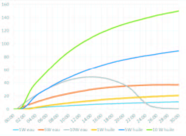
The tests were performed with pure water, 25%, and 50% glycol added water, as they are representative of liquids used in central heating and solar heating circuits, and with peanut oil representative of liquids used in food applications.
 |
 |
 |
| At no flow condition, values of temperature difference 50 mm top and 50 mm bottom of heating element. It is possible to see huge temperature differences, mainly in oil. Note: On the water test with 10W/cm² load, after 6 minutes, the water around the heating element starts boiling, and the temperature difference decreases progressively, because of the convection provided in the water by ebullition. |
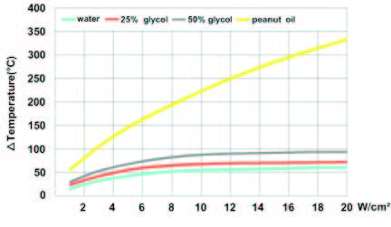
At no flow condition, difference between heating element surface temperature and liquid temperature measured 50mm above the heating element, at various surface loads. Heating element is fully immersed. (Measurements made 10 minutes after energization) Note: above 8W/cm², there is no increase of temperature difference in water and water + glycol, because liquid in contact with heating element starts to boil and energy is used for vaporization. |
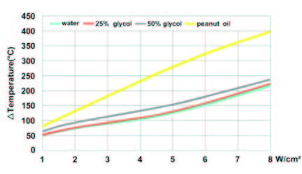
At no flow condition, this is a simulation of what happens when the heating element starts to rise from the liquid level. (Half immersed, measurement made after 10 minutes). Heating element surface temperature rises sharply. Note: for oil, the flash point (320°C) is reached at 7W/cm² load, and auto-ignition may occur (Fire hazard) |
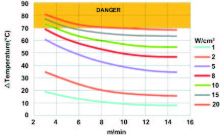
1.3 Immersion heaters used in tanks or containers with permanent water flow
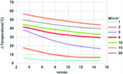
In applications with permanent flow, the important parameter is the velocity of the liquid around the heating element.
In the graphs below, the speed is given in meters per minute.
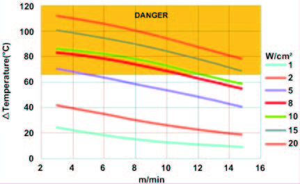
The temperature data from these curves is the difference between the surface temperature of the heating element and the fluid temperature, measured 50mm above the heating element. The tests were performed with pure water, and water with glycol addition of 25% and 50%, for the surface load of 1 to 20 W/cm². The heating elements are completely submerged.
 |
 |
 |
| In pure water, in all cases of this test, the boiling temperature is not reached when the water is at less than 40°C when it comes into contact with the heating elements. However, for an inlet temperature of 40°C the temperature of 65 ° C is reached in all cases with a load of 8W / cm² and more. |
In water with 25% glycol, commonly used in heating circuits, the boiling temperature is reached at speeds less than 6 m/min from 8W/cm² with a water inlet temperature of 40 ° C. All loads greater than 8W/cm² reach the boiling point. | In water with 50% glycol, used in heating circuits which have to withstand very low temperature, the boiling temperature is reached for speeds less than 8 m/min and loads of 5W/cm² with an inlet temperature water of 40 ° C. All loads greater than 5W / cm² reach the boiling point. |
2. Selecting the fitting or the flange
2.1 Fitting material
It is important to consider the , whose corrosion resistance must be compatible with the liquid. Most heaters use a threaded brass fitting, brazed to the heating elements. For applications where the brass is not allowed, a stainless steel fitting, made of 304L or 316L, can be used. It can be brazed with copper alloy or TIG welded for the most difficult cases.
The light flange-mounted immersion heaters, such as that used in washing machines and water heaters, use AISI 304 stamped flanges, cheaper than brass and guaranteeing a better pressure resistance.
Immersion heaters for industrial applications use standard pipe flanges.
2.2 Method of attachment of the heating element to the flange or the fitting
This attachment must meet various requirements, including: provide a good seal, withstand the temperature of the liquid and the surface temperature of the heating element, provides mechanical retention, corrosion resistance.
| Type | Sealing | Temperature | Mechanical retention | Corrosion resistance |
| Tin soldering | Good if no mechanical stress or vibrations. Soldering is difficult on stainless steel. |
Max 120°C | Poor to average | Poor |
| Epoxy bonding | Good if no mechanical stress or vibrations. | Max 80°C | Poor | Good |
| Copper alloy brazing | Good, but risks of leakage eventually undetectable in production. |
Max 300°C | Superior | Average |
| TIG welding | Superior | Max 450°C (304L) | Superior | Superior |
2.3 Threads
In Europe there are two common thread types used on immersion heaters fittings.
-Threads according to ISO228-1, also said BSPP or cylindrical gas thread (G),
– 2mm pitch metric thread according ISO965-1, little used, which was the subject of an attempt to standardize in the middle of the 20th century .
The threads are still sometimes described, particularly in France, according to their internal and external diameters.
All these threads are parallel, and therefore requiring a gasket surface to ensure proper sealing. They are mounted on female nozzles, or through wall with a nut.
Selecting a thread diameter is mainly imposed by the minimum possible bending diameter of sheathed elements. Threads of 1″ and below are therefore used on the cartridge heaters.
The main threads are:
| Standard size | 1/2″ (15-21) | 3/4″ (20-27) | 1″ (26-34) | 1″ 1/4 (33-42) | 1″ 1/2 (40-49) | M45X200 | 2″ (50-60) | 2″ 1/2 (66-76) | M77*200 |
| Outside dia | 21 mm | 26.4 mm | 33.3 mm | 41.9 mm | 47.8 mm | 45 mm | 59.6 mm | 75.2 mm | 77 mm |
2.4 Rotation
Heaters are often screwed on nozzles welded on the wall of a tank or heater. The seal is obtained by tightening a gasket, it is impossible to predict in advance what will be the position of the fitting and its connection box when tightening will be effective.
Therefore we have designed a technical solution to facilitate the enclosure positioning after fitting tightening.
The unique design of immersion heater rotating brass fittings used in the products of this catalog
– Fit the full range of immersion heater enclosures, starting from the 1″1/4 fitting
– Compact size and short length result in reduced weight ( save + / -30% compared to double thread fittings)
– Allows a 360° rotation of enclosure
– Thread clearance for captive gasket
– Large chamfer facilitating correct assembly
– Large machined gasket seat
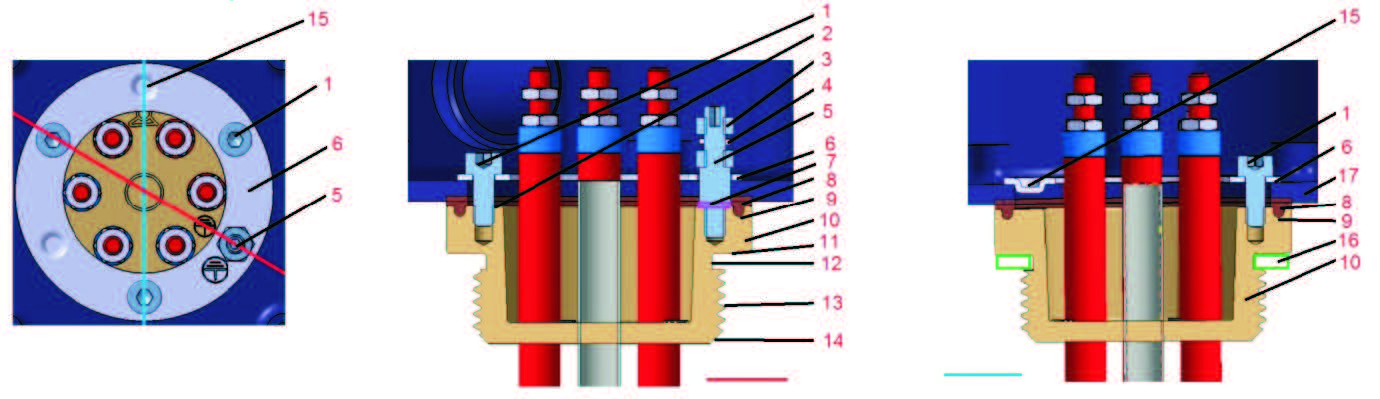 |
||
| 1: Assembly screw, M4 or M5 2: Machined flat surface 3: Grounding nuts 4: Dented washer and saddle 5: Grounding stud M4 or M5 6: Rotation ring 7: Dented washer |
8: Silicone waterproof gasket 9: Anti-creep groove 10: Fitting 11: Machined flat surface 12: Unlosable gasket groove 13: Metric or BSPP thread |
14: Large chamfer 15: Centering embossing 16: Unlosable gasket 17: Enclosure |
Assembly on enclosures:
– Through a hole in the enclosure. The enclosure is sandwiched between the fitting and a stamped inner ring. Bumps in the ring provide self-centering. This stamped ring costs only 10% of the conventional threaded inner rings.
Gasket between fitting and enclosure
-The 4 x 2 mm section, 50 Shore silicone gasket with anti-creep rib, absorbs flatness differences, and remains in place during tightening.
– Guaranteed IP65 ingress protection up to 200 ° C between fitting and enclosure.
Inner stamped ring
– The clamping with 3 BTR screws at 120° ensures a good pressure distribution and an excellent mechanical strength.
These screw positions increase the clearances between the screw heads and live parts of the heating elements
– The recessed hexagonal hole screw heads allow easy and stable entry of hex wrench when adjusting angular position
– Ring made of stainless steel for better durability
– Unalterable stamped earthing logo
Rohs compliance
According to the Directive 2011/65/ dated June 8, 2011 (Rohs), copper alloys are allowed to have a maximum of 4% by weight of lead as an alloying element. (Provisions of Article 4 and paragraph 1 of Annex II, limit value set by 6c of Annex III).
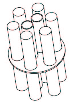
| Maintaining the tubes In products having several heating elements and thermowells, it is necessary, from a certain length (typically all 40cms in dia. 8mm; 50cm in 10mm dia.; 60 cm in dia. 12mm), to fasten all the tubes in order to prevent them to collide. This is accomplished by one or more grids. |
 |
Non-heating zone, also said cold zone
The non-heating zone is located under the fitting or under the flange. It avoids that the heating elements heat up by thermal conduction the electrical connection ends and the housing. An usual value of this non-heating zone is 50 mm (for the immersed portion).
3. Selecting the Enclosure
3.1 Plastic or aluminum enclosure?
Traditionally immersion heaters enclosures are made of aluminum, as this was the most suitable material in the middle of the 20th century, when the choice of plastic materials was limited to thermosetting resins, Bakelite type.
However, the plastic enclosures offer, in addition to a wide variety of moldable shapes, interesting characteristics of electrical insulation, resistance to chemicals and corrosion. They are also generally cheaper because they do not require painted surface protection.
However, they were often criticized for their low mechanical or thermal resistance. The fault is not to the plastic itself, but to the designers of these enclosures, often from Southern Europe, who have often favored the cheapest plastic and the lowest weight of the material, at the detriment of strength and technical requirements.
3.2 Plastic enclosures
A good plastic enclosure must provide a good resistance to corrosion, shock, water ingress, UV, temperature.
The choice of the plastic material and thickness will depend on electrical safety, strength, UV resistance for outdoor use, and compliance with European directives Rohs 20220/95 / EC and Reach
We have therefore chosen plastics with exceptional environmental resistance characteristics, thermal and electrical. The thicknesses used are defined to meet the impact resistance requirements.
Comparison of main plastics used in immersion heaters enclosures
| Raw material | Temperature of deformation under load (ISO 75, method A) | Impact resistance on a 3 mm thick plate at 25°C (EN50102) | Resistance loss, after UV test 1000h* (ISO4892-1) | Flammability (UL94) | Mechanical breakage ISO 527 ASTMD638 | GWFI Glow wire test (IEC 60695-2-12) | Comments |
| ABS | 92°C | 9.4 (IK08) | Bad: 80% mechanical resistance loss after 1000H | UL94-HB | 50 Mpa | 650°C | The least expensive material. Poor temperature resistance, very poor insulation and mechanical feature. Not allowed for immersion heater enclosures. |
| PS | 75)c | 9.8 | Medium: 25% mechanical resistance loss after 1000H | UL94-HB à UL94-HB | 23 to 32 Mpa | 750 to 960°C | Inexpensive material. No temperature resistance, low mechanical strength. Not allowed for immersion heater enclosure. |
| PA66 | 100°C | 2.9 (IK06) | Medium: 22% mechanical resistance | U94-VO | 80 to 85 Mpa | 650 to 750°C | Good mechanical resistance but low temperature and UV resistance. Low electrical insulation. non recommended for immersion heater enclosure. |
| PC | 135°C | 21.2 (IK10) | Good: 11% mechanical resistance loss after 1000H | UL94-5V | 70 Mpa | 850°C | Avoid if possible for immersion heater enclosures, due to its average resistance to UV and glow wire flammability. Fiberglass reinforced, with black pigment, however, can be used, as this plastic has a good temperature resistance. |
| PC-ABS | 80)c | 11.6 (IK09) | Good: 18% mechanical resistance loss after 1000H | UL94-VO | 60 MPA | 960°C | Genrally suitable for indoor use immersion heater enclosure, if there is no possible high temperature |
| PC-ABS + 20% FG | 120°C | 9.1 (IK08) | Good: 15% mechanical resistance loss after 1000H | UL94-VO | 77 MPA | 960°C | Suitable for immersion housings for indoor and outdoor. Less expensive than glass fiver reinforced PA66. Has a good surface finish. |
| PA66, 20% FG | 250°C (Peak)
120°C (Permanent) |
IK10
(The most stringent) |
Excellent: 7% mechanical resistance loss after 1000H | Ul94-Vo et UL94-5V (the most stringent) | 150 Mpa | 960°C | The best technical choice: the highest technical characteristics in temperature, UV, mechanical strength adn electrical insulation. However, it is the most expensive material (in the UL94-VO and GWFI 960 types). |
Note on IK Classes: to be IK rated, a material must withstand a shock greater than or equal to the following values: 1 joule = IK06,
IK07 = 2 Joules, IK08 = 5 Joules, 10 Joules = IK09, IK10 = 20 Joules. Therefore, an IK10 box is on average 2 times stronger than IK09, 4 times more than IK08, 10 times more than IK07 and 20 times more than IK06.
* UV resistance is improved by the addition of black pigment (black carbon), and it is the main reason for the black color of the boxes intended for outdoor use.
Aluminum enclosures:
These enclosures provide unmatched mechanical and thermal resistance, while remaining relatively mild. Good thermal conductors, they evacuate smoothly the energy received by heating elements conduction. However, they suffer from the following disadvantages:
They are not electrically insulated, and internal wiring must be protected accordingly, and they need to be grounded.
They are susceptible to galvanic corrosion in wet conditions, and especially when in contact with metals such as zinc or galvanized steel.
If the surface is not protected, they will also be quickly covered by an oxidized layer.
Therefore, good aluminum housings must be grounded and protected against galvanic corrosion and receive an epoxy paint layer when used outdoors.
Our aluminum enclosures were therefore designed to meet these requirements. For this purpose, they have:
– Stainless steel nuts and screws to prevent galvanic corrosion between the screw and nut.
-Crimped nuts with epoxy seal to prevent galvanic corrosion between nut and aluminum.
-Plastic washers under the heads of the cover screws to prevent galvanic corrosion between the head of the nut and cover.
-They are coated with a baked epoxy paint applied on a sandblasted surface (to improve epoxy bonding to surface) thus providing a durable and reliable protection
In addition, to reflect the wishes of users, they have in addition the following advantages:
-Captive stainless steel lid screws with dual slots Phillips head.
-These screws are mounted in “Nylstop” locknuts, which prevent their loosening by vibration.
-Two internal grounding threads, equipped with M4 stainless steel screws and washers .The larger models are also equipped with two external grounding threads.
-3mm and sometimes 4mm wall thickness that permits tapping of threads, for cable glands, caps and other immersion heaters fittings.
-Internal studs on the cover that provides the possibility to mount thermostats with sealed wall crossing axis
-Internal studs on lower part of enclosures for mounting terminal blocks or accessories that are not secured to the cover
– Recessed places for labels or name plates that can be riveted or glued, to avoid intentional or unintentional removal.
– Silicone foam cover seal: temperature resistance up to 200°C and good compensation of surface irregularities in the sealing surfaces
Cable and wire outputs on cartridge heaters
The outputs of wires or cable on cartridge heaters can be protected by silicone filler cap, or by an over-molded PA66 boot. This provides an ingress protection degree higher than IP65.
4. Selecting temperature control and safety devices
4.1 Selection of types of regulation
Traditionally the immersion heaters, when they are equipped with a temperature control device are using a mechanical thermostat, and its sensor is mounted in a pocket located between the heaters. This is a compact and reliable solution.
It is also possible now, to produce compact immersion heaters with electronic temperature controllers, combined or not with a fail-safe manual reset safety thermostat.
Comparison of mechanical and electronic control systems that can be incorporated in immersion heaters
| Device | Control accuracy and differential | Ambient temperature | Electrical rating | Comments |
| Single pole bulbe and capillary thermostat | Set point accuracy: +/-3°C to +/-5°C, vary upon temperature ranges.
Differential: 2.5 à 4°C, varies upon temperature ranges |
80°C (temperature ranges up to 60°C)
125°C (temperature ranges up to 110°C) |
16A 250V
(Up to 3 x 32Av 400V in products with built-in power relay) |
Compact, can be mounted in all enclosures above 9ST3.
Usually used up to 3000W single phase |
| Single pole bulb and capillary thermostat + manual reset single pole safety thermostat | Set point accuracy: +/-3°C to +/-5°C, vary upon temperature ranges. Differential: 2.5 à 4°C, varies upon temperature ranges. |
80°C ( temperature ranges up to 60°C) 125°C (temperature ranges up to 110°C) |
16A 250V (Up to 3 x 32A 400V in products with built-in power relay) |
Usually used up to 3000W single phase. Safer solution than a single thermostat. This combination is possible only in enclosures from 9ST6 |
| 3 pole bulb and capillary thermostat | Set point accuracy: +/-4°C to +/-6°C, vary upon temperature ranges. Differential: 4 à 6°C, varies upon temperature ranges. |
80°C ( temperature ranges up to 60°C) 125°C (temperature ranges up to 110°C) |
3 x 16A 250V 3x16A 400V |
Allows to control 3 phase loads in a compact form. Can be mounted in any enclosure above 9ST4, excluding 9STC. |
| 3 pole bulb and capillary thermostat + 3 pole manual reset safety thermostat | Set point accuracy: +/-4°C to +/-6°C, vary upon temperature ranges. Differential: 4 à 6°C, upon temperature ranges. |
80°C ( temperature ranges up to 60°C) 125°C (temperature ranges up to 110°C) |
3 x 16A 250V 3x16A 400V |
Only compatible with 9ST7 boxes |
| Combined device, 3 pole temperature control and manual reset safety thermostat | Set point accuracy: +/-5°C to +/-8°C, vary upon temperature ranges. Differential: 8 à 12°C, varies upon temperature ranges. |
80°C ( temperature ranges up to 60°C) 125°C (temperature ranges up to 110°C) |
3 x 20A 250V 3x16A 400V |
Simple, but huge calibration drift upon ambient temperature. Compatible with 9ST5 enclosure and above (except 9STC) |
| Electronic temperature controller with digital display | Display 1/10°C under 100°C. °C display up. Accuracy +/-1°C. Adjustable differential |
60°C | 1 x 16A 250V or 3 x 16A 250V Up to 3 x 32A 400V in products with built-in power relay, or up to 25A 250V In products using Solid state relay. |
Permanent illuminated digital display of the liquid temperature. For on-OFF or PID temperature control upon models. Compatible with 9ST8, 9STB, 9ST9, 9STA enclosures |
| Electronic temperature controller with digital display and manual reset bulb and capillary thermostat |
Display 1/10°C under 100°C. °C display up. Accuracy +/-1°C. Adjustable differential |
60°C | Up to 3 x 32A 400V in products with built-in power relay, or up to 25A 250V In products using Solid state relay. |
Permanent illuminated digital display of the liquid temperature. For on-OFF or PID temperature control upon models. Compatible with 9ST8, 9STB, 9ST9, 9STA enclosures |
Inside or outside setting?
The choice of access to the thermostat setting is dependent on the application.
-An internal access, which requires unscrewing the housing cover screws limits the possibilities of modification by unauthorized persons, and it is possible to seal the cover screws in order to check if someone has accessed this setting
– An access by an external knob is preferred when this adjustment must be changed regularly in the normal working operation of the heater. If needed, accessories like adjustable stops (see last section of this catalog) will allow setting high or low adjustment limits by the user. However, a device with an external knob is more brittle, less protected from impact and has a lower water and dust ingress protection. It is therefore not recommended for outdoor use.
-A Compromise between internal and external access is access under cap. Unscrewing, by means of a screwdriver or of a coin of a M25 cap provides access to a miniature knob on dial. Protection against water or dust ingress, and impact strength are not modified, provided that the cap is correctly reassembled.
Thermowells (also said « pockets »)
Thermowells are used to place temperature measurement sensors in a liquid-tight tube to sense the temperature of the liquid in which the heater is immersed. The location of the thermowell is important because it determines the accuracy of the measured temperature, and the response time required to measure a temperature change.
A thermowell located in the center of the heater, at a distance of 10 to 20mm of the tubular heating elements, provide a good measure of the average fluid temperature, and will therefore be adapted to a control system.
If a safety thermostat is installed, and if it is intended to measure overheating of the liquid, a similar positioning of the thermowell is great. But if it is intended to detect dry running and avoid the destruction of the item or the risk of fire due to dry running, this thermowell, especially the part where is located measuring element or the thermal fuse, should be very close to the heating elements that come out of the liquid when it goes down.
If, in this case, the heating elements have a high surface load, a copper tube thermowell, better heat conductor than stainless steel, is recommended to reduce the response time. Do not hesitate to contact us.
Use and installation of thermal cut out (TCO)
The ultimate security in an immersion heater is to use a thermal fuse. Two solutions exist:
– One is to install the wired TCO in a thermowell close to a heating element so that the TCO is triggered if the heater is used when not submerged. This solution allows the change of the fuse during a maintenance operation. This mounting requests 9mm I.D. thermowell (larger than that usually used for thermostats or temperature sensors).
– The second is to embed the TCO in the cold zone of the heating element, but in this case the temperature response time is slower, and this mounting does not permit the change of the TCO when it has trigged. The entire immersion heater must then be replaced.