Introduction to the use of solid state relays (SSR) and comparison with electromechanical relays
The solid state relay, also called solid state contactor or SSR (English acronym for Solid State Relay) is the electronic equivalent of the electromechanical power contactor.
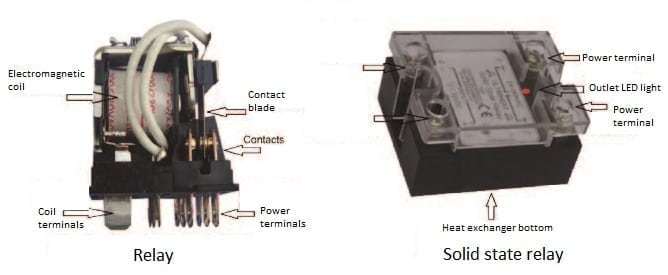
The relay or electromechanical contactor: The coil is made of a very large number of turns of a very thin copper wire. When a sufficient current goes through the coil, it produces a magnetic field that attracts the movable part and moves the reeds with electrical contacts. When the current no longer flows in the coil, the contacts return to their initial position thanks to a restoring spring.
The solid state relay: the input circuit, equivalent to the contactor coil is electrically isolated from the power circuit with an optocoupler (also known as photocoupler), composed of a LED and a phototransistor. This miniature electronic component can separate two electronic or electrical circuits whose grounds are not at the same voltage. The input circuit command is usually done by of low DC voltage pulses consuming a few milliamps. This input circuit controls a power circuit usually consisting of thyristors or triacs.
Accurate controls, particularly those with PID action, may require very high heating opening and closing frequencies, with durations sometimes less than one second. These frequencies cause the electromechanical contactors quick wear but do not affect the static switches. It is the same for On/Off controlled applications with low differential (hysteresis) of systems submitted to sudden changes in temperature.
Over the past two decades, the dimensions and characteristics of solid state relays connection were gradually standardized, and most models are now interchangeable.
General comparison between solid state and electromechanical relays
| Radio interferences |
Wear | Noise | Dimensions | Overheating | Insulation | Coût | |
| Solid stare relay | 99% removed by the cut to zero technique and filters | No | No | Small except if a heatsink is required | Significant, often requires a heatsink | Open position: Residual leakage current |
Medium, dropping |
| Electromechanical relay |
Few interferences | The electrical contacts wear at each cycle | Click | Large for power contactors |
Low | Open position: no current flows |
Low |
Installation example of solid state relays in an aluminum Ultimheat
housing (thermal compound in red).
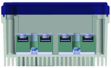
Installation example of solid state relays in an aluminum Ultimheat housing (thermal compound in red).
Heat dissipation: approximately 0.3% of the average power (about 1W per Ampere rms) passing through is dissipated by Joule effect in the solid state, and must be evacuated.
For instance: a solid state 20A 240V relay, operating at 100% power, dissipates around 15 watts, which is sufficient in the case of a control box, to raise its internal temperature of
30-40 ° C. SSRs have a lower surface of aluminum which is used to remove that power.
The temperature of this wall can not exceed 115 ° C. Heat sinks should be provided to properly exhaust the heat generated. For this, it is necessary that this surface has an excellent thermal contact with the wall it is mounted on. A contact grease is necessary to improve the exchange. For Ultimheat boxes provided for solid state relays, the heat dissipation is achieved by aluminum fins incorporated into the rear of the case itself. This does not lead to any size or cost increase, unlike other concepts using separate heatsinks.
Residual current: an important parameter to consider when installing solid state relays is that there always remains a few milliamperes residual current when turned “OFF” (Unlike most electromechanical contactors where no current flows when the contacts are open).
Transcient overvoltages: the sensitivity of solid state relays to transcient overvoltages, which were an early weaknesses of these products, is now greatly reduced by using protective circuits generally based on MOV varistors.
Current rating: in the same way as electromagnetic relays, the current rating of solid state relays is given for a resistive load. Because of the extra currents of inductive opening and breaking loads , as well as extra power-currents of self-regulating heating elements, it is necessary to apply a reduction coefficient of the nominal current ratings in these applications.
Table of current rating reduction coefficients
| Resistive load | Filament lamp | Electromagnetic coil | Transformer | Single phase motor | Three phase motor | Self-regulating heating cables* |
| 1 | 0.8 | 0.5 | 0.5 | 0.12/0.24 | 0.18/0.33 | 0.6 |
*Average value, depending on cable ambient temperature at startup, see the manufacturers manuals and Standard CEI60898
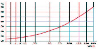
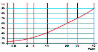
Temperature of the SSR rear side according to the dissipated power (Ambient temperature = 25°C, Blue lines =safety thermostat set points)
Aluminium main housing
(180x130x63mm) without fan
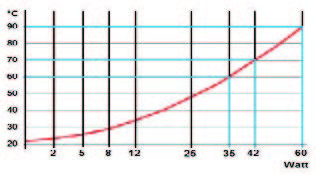
Aluminium additional housing
(175x86x40 mm)
Aluminium main housing
(180x130x63mm) without fan