Electrical protection classes
The housings are designed to protect electrical equipment located inside. This protection must be considered in the electrical and environmental angles.)
Sets Y0 to Y5 describe products with protection classes which are different and intended for different applications. This introduction allows to understand and define the specifications for an application.
For further information on the specific protection explosive atmospheres, see catalogs No. 4 and No. 2 for the resistance of plastics and elastomers to temperature and UV.
Chapter 1: Electrical protection
Chapter 2: Ingress protection (IP)
Chapter 3: Mechanical protection (IK)
1. Electrical protection classes
There are two main types of electrical protection, protection against the risk of direct contact (functional isolation) and protection against indirect contact hazards.
The functional isolation is not sufficient in case of electrical failure and it is necessary to add protection against the risks of indirect contacts, which can be achieved by the following means:
- The earthing of all metal
- Double or reinforced
- A low voltage supply via a transformer.
The combination of these protections determines the class of electrical protection device.
The 4 electrical safety levels of electrical devices
| Class | Symbol | Description |
| 0 | Equipment with only functional insulation but not binding to the metal masses. Banned in Europe. | |
| 1 |  |
Material with a functional isolation and earthing of metal masses. These devices must be connected to earth. |
|
2 |
 |
Equipment with dual insulation of live parts (functional isolation and physical). No earthing of metal parts. This ensures that no double insulation accessible part may be subject to dangerous voltages even after a first insulation fault. The advantage of this class of appliances is a higher protection to the user regardless of the electrical sockets used (With or without earth terminal). These devices must not be connected to earth. |
|
3 |
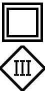 |
Equipment class 2 transformer with a SELV (Safety Extra Low Voltage). |
Earthing provisions of metal enclosures and fittings
The design of the grounding connections was made to meet all the points of the EN60335-1 standard, and to ensure a safe grounding, and specially the following requirements:
EN60335-1, § 27.1: Accessible metal parts of class I appliances that may become live in the event of an insulation fault, shall be permanently and reliably connected to an earthing terminal within the appliance.
To meet this normative obligation, our metal housings and our brass and stainless steel fittings are equipped with at least one grounded terminal. For stamped sheet metal housings, the grounding is performed by a welded terminal having at least two soldering points.
EN60335-1, § 27.2: The clamping means of earthing terminals shall be adequately secured against accidental loosening. It shall not be possible to loosen the conductors without the aid of a tool.
To meet this normative obligation, earthing is made by screws needing a screwdriver to screw and unscrew, and have dented washers.
EN60335-1, § 27.4: All parts of the earthing terminal intended for the connection of external conductors shall be such that there is no risk of corrosion resulting from contact between these parts and the copper of the earthing conductor or any other metal in contact with these parts.
To meet this normative obligation, the choice of terminal materials and screws is made taking into account the galvanic voltage between materials, to avoid bimetallic corrosion, and favoring, whenever possible, the stainless steel screws and terminals.
EN60335-1, § 28.1: Earth connections which failures may provide a lack of earthing continuity shall withstand the mechanical stresses occurring in normal use.
Screws used for connections providing earthing continuity shall screw into metal.
To meet this normative obligation, earth terminals withstand more than one and a half times the nominal tightening torque required by the standards and are threaded in the mass of the metal of the housing or fitting.
EN60335-1, § 28.2 Connections providing earthing continuity shall be constructed so that contact pressure is not transmitted through insulating material that is liable to shrink or to distort.
- Thread-cutting (self-tapping) screws shall not be used if they are likely to be operated by the user or
- At least two screws must be used for each connection providing earthing continuity unless the screw forms a thread having a length of at least half the diameter of the
In order to meet this normative obligation, the earthing terminals of the connectors are designed so that, even when they are used with a plastic housing with an interposed gasket, the tightening of the conductor is done only on metallic parts.
EN60335-1, § 28.2: Self-tapping screws shall not be used if they can be used by the installer or the user. At least two screws shall be used for each earth connector unless the screw forms a thread having a length of at least half the diameter of the screw.
To meet this normative obligation, self-tapping screws are never used for grounding, and when the grounding is performed by a screw in a tapping, the length of it is always greater to the value given by the standard.
28.4 Screws and nuts that make a mechanical connection between different parts of the appliance shall be secured against loosening if they also make connections providing earthing continuity.
- Sealing compound that softens on heating provides satisfactory security only for screw connections not subject to torsion in normal
To meet this normative obligation, the screws of metal covers include a mechanical device avoiding accidental loosening. No sealing compound is used on the screws.
2. IP protection (Ingress protection)
The first 2 characters of IP codification (upon IEC 60259)
The IP rating defined by the IEC 60529 specifies the degree of protection against ingress of solid bodies (first digit) and against the ingress of water (second digit). Third and fourth characters, optional, provide information on the level of protection. The classification is done by increasing efficiency. There are 7 levels against solid (0: no protection, 6 fully protected) and 9 levels against water (0: no protection, 8: protected against immersion under pressure).
For example, “IP21” means protected against solid objects greater than 12.5 mm (e.g. a finger) and resistant to condensation.
Caution: Some IP Protection grades can be given for a specified enclosure position.
X letter in the codification:
The letter X is used in any place in the code where specifying a digit is meant to be avoided. There may be various reasons for choosing this coding variant, such as marketing considerations. Thus, e.g. an IPX7 rating for a consumer device specifies that the device has water protection up to limited immersion, but gives deliberately no information as to whether the device has any protection against mechanical ingress or dust. Among other common IP ratings using the letter X are IPX4. IP2X is frequently used on electrical items to specify the item must prevent finger access to live terminals i.e. plug sockets are IP2X.
2.2 First digit (Solid particle protection)
The first digit indicates the level of protection that the enclosure provides against access to hazardous parts (e.g., electrical conductors, moving parts) and the ingress of solid foreign objects.
The first digit of the IP marking is not required by EN 60335-1
| IP1X | IP2X | IP3X | IP4X | IP5X | IP6X | ||
 |
 |
 |
 |
 |
 |
||
| First digit | Protection type | Effective | |||||
| 0 | No protection | No protection against contact and ingress of objects | |||||
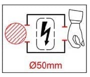
| 1 | Protected against solid particles >50 mm |
Protected against any large surface of the body, such as the back of a hand, but no protection against deliberate contact with a smaller body part | |||||
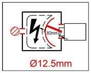
| 2 | Protected against solid particles >12.5 mm |
Protected against fingers or similar objects | |||||
| 3 | Protected against solid particles >2.5 mm |
Protected against tools, thick wires, etc. | |||||
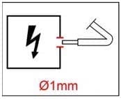
| 4 | Protected against solid particles >1 mm |
Protected against most wires, screws, etc. | |||||
| 5 | Dust protected | Ingress of dust is not entirely prevented, but it must not enter in sufficient quantity to interfere with the satisfactory operation of the equipment. Completely protected against contact. | |||||
| 6 | Dust tight |
Completely protected against ingress of dust. Completely protected against contact. |
|||||
2.3 Second digit (Liquid ingress protection)
The second digit indicates the level of protection that the enclosure provides against harmful ingress of water.
| IPX1 | IPX2 | IPX3 | IPX4 | |||||
 |
 |
 |
 |
|||||
 |
 |
 |
 |
|||||
| Second digit | Protection type | Effective protection | Test description | |||||
| 0 | Not protected | |||||||
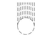
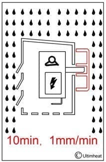
| 1 | Dripping water | Dripping water (vertically falling drops) shall have no harmful effect. | -Water equivalent to 1 mm rainfall per minute
-Test duration: 10 minutes |
|||||
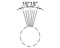
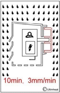
| 2 | Dripping water when tilted up to 15° | Vertically dripping water shall have no harmful effect when the enclosure is tilted at an angle up to 15° from its normal position. |
– Water equivalent to 3 mm rainfall per minute. – Test duration: 10 minutes |
|||||
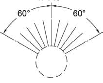
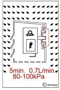
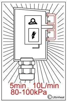
| 3 | Spraying water | Water falling as a spray at any angle up to 60° from the vertical shall have no harmful effect. | – Water volume : 0.7 liters per minute
– Pressure: 80-100kPa – Test duration: 5 minutes |
|||||
| 4 | Splashing water | Water splashing against the enclosure from any direction shall have no harmful effect. |
– Water volume: 10 liters per minute
– Pressure: 80-100kPa – Test duration: 5 minutes |
|||||
| IPX5 | IPX6 | IPX7 | IPX8 | |||||
 |
 |
 |
 |
|||||
| Second digit | Protection type | Effective protection | Test description | |||||
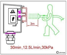
| 5 | Water jets | Water projected by a 6.3 mm dia.nozzle against enclosure from any direction shall have no harmful effects. |
– Water volume: 12.5 liters per minute – Pressure: 30 kPa – Distance: 3 m – Test duration: 3 minutes |
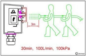
|||||
| 6 | Powerful water jets | Water projected in powerful jets (12.5 mm nozzle) against the enclosure from any direction shall have no harmful effects. | – Water volume: 100 liters per minute – Pressure: 100 kPa – Distance: 3 m – Test duration: 3 minutes |
|||||
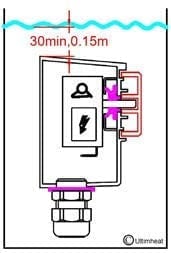
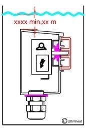
| 7 | Immersion up to 1 m | Ingress of water in harmful quantity shall not be possible when the enclosure is immersed in water under defined conditions of pressure and time (up to 1 m of submersion). | – Immersion at depth of at least 1 m measured at bottom of device, and at least 15 cm measured at top of device – Test duration: 30 minutes |
|||||
| 8 |
Immersion beyond 1 m |
The equipment is suitable for continuous immersion in water under conditions which shall be specified by the manufacturer. Normally, this will mean that the equipment is hermetically sealed. However, with certain types of equipment, it can mean that water can enter but only in such a way that it produces no harmful effects. |
Test duration: continuous immersion in water. |
|||||
2.4 First additional letter
Additional letters that can be appended to classify only the level of protection against access to hazardous parts by persons
| Letter | Protected against access to hazardous parts with |
| A | Back of hand |
| B | Fingers |
| C | Tools |
| D | Wires |
Second additional letter
Further letters can be appended to provide additional information related to the protection of the device
| Letter | Meaning |
| H | High voltage device |
| M | Device moving during water test |
| S | Device standing still during water test |
| W |
Weather conditions |
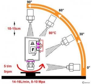
2.5 IP69K (DIN 40050-9)
 |
Description |
|
Specific ingress protection rating for high-pressure, high-temperature washing applications. |
|
| Test description | |
| – Water volume: 14-16L liters per minute – Water temperature: 80°C – Pressure: 8–10 Mpa (80–100 bar) – Distance: 10 to 15cm from the tested device at angles of 0°, 30°, 60° and 90° for 30s each. The test device sits on a turntable that rotates once every 12s |
2.6 Examples of ingress protection ratings requested by standards and applications
An IP protection rating may be required by specific standards such as NF15100 (domestic electrical installation rules), EN60335-xx (design rules for electrical appliances) and machine-specific standards. Hereafter are the main specifications extracted from these standards.
| Bath rooms, swimming pools and assimilated |
These rooms are divided in 4 area volumes: 0,1,2,3. These volumes and installation rules are described in the French standard NFC15100, International standard Cenelec HD384 and European standard IEC 60364. | ||
| Areas | Minimal IP requirements | Electrical protection | |
| 0 | All electric heaters are prohibited. Other equipments: Bathrooms: IPX7 Pools and similar: IPX8 |
SELV limited to 12V DC or 30V AC | |
| 1 | All electric heaters are prohibited. Other equipments: Bathrooms: IPX4, but IPX5 if this volume can be subjected to water jets for cleaning in public baths. Pools and similar: IPX5 |
SELV limited to 12V DC or 30V AC | |
| 2 | Bathrooms: IP24 mini heaters are authorized Other equipments: IPX3, but IPX5 if this volume can be subjected to water jets for cleaning in public baths. Indoors Pools: IP24 mini heaters authorized Other equipments: IPX2, but IPX5 if this volume can be subjected to water jets for cleaning. Outdoors Pools: IPX5 |
– Class 2 devices – Controls should not be accessible from the shower or bath. – Heaters must not be powered by a wall mounted socket. – Line must be protected by a 30 mA residual current circuit breaker |
|
| 3 | Bathrooms: IP21 mini heaters are authorized Other equipments: IPX1 Pools: Heaters authorized IP21 mini Other equipments: IPX1, but IPX5 if this volume can be subjected to water jets for cleaning. Outdoors Pools: IPX5 |
– Class 1 or Class 2 devices – Heaters must not be powered by a wall mounted socket. – Line must be protected by a 30 mA residual current circuit breaker |
|
| Saunas | Electrical equipment must have an IP 24 minimum protection rating | ||
| Under floor heating | The heating elements intended to be embedded in a concrete or other similar material must be IPX7 | ||
| Electrical devices that are permanently outdoor |
The degree of protection shall be at least IPX4 | ||
| Residential, Offices, Schools | Generally clean, dry and free from harmful deposits of dust, but some condensate may be present due to atmospheric conditions. Minimum protection is typically IP2X for dry conditions. | ||
| Control rooms/ Sub-Stations | Generally dry and free from harmful deposits of dust, but some condensate may be present due to atmospheric conditions. Where access is restricted to skilled or instructed persons, IP2X is the typical minimum requirement for dry conditions. |
||
| Commercial, Light Industrial | These premises may not be clean, but normally dry and free from harmful deposits of dust. Suitable minimum protection: – Where condensate is not present: IP2X – Where condensate may be present: IP21. – Equipment installed within range of fire sprinkler systems: IP22. |
||
| Machine control equipment | Where fluids may be present, e.g. lathes, millers etc., minimum protection typically requested is IP54. Consideration should also be given to the corrosive properties of certain fluids |
| Heavy Industrial, Chemical | These environments are not usually totally clean, with possible presence of corrosive elements and harmful deposits of dust. Protection to IP54 will be typically required, with special consideration given to the corrosion resisting properties of the enclosure. When explosion risks exist, enclosures and equipment should meet the specifications of these environments |
|
Food Processing |
Will vary depending on the type of food being processed and the possible requirement for washing down. Where fine powders are present, a minimum of IP53 should be used. This should be increased to IP54/65 if the equipment needs to be washed or hosed down. If the equipment should be washed with a jet of hot or cold water under high pressure, it is possible that the IP 65 rating is insufficient and that the IP69K is required |
|
Dump trucks, cement mixers, food industry, car wash |
In these high-pressure, high-temperature wash-down applications, enclosures must not only be dust tight (IP6X), but also able to withstand high-pressure and steam cleaning. The recommended protection rating is IP69K (DIN40050-9) |
| Weather proof equipment | If subjected to exposure to any specific weather condition, an agreement between the User and Manufacturer is necessary, with consideration given to specific testing conditions, including the corrosion resisting properties of the enclosure, fittings and cable glands |
4. Other classifications
NFC 15100 standard also refers to a “water drop” marking that household appliances and lightings can wear depending on their protection rating. This marking is different from the IP marking. Double marking, the water drops and the IP code, is not allowed because the tests are different.
| Description | Protected against vertical water drops | Protected against rainfall | Protected against splashing water |
Protected against water jets | Protected against immersion up to 1m |
| IP equivalent | IPX1 | IPX3 | IPX4 | IPX5 | IPX7 |
| Standard logo | |
 |
 |
 |
 |
5. NEMA (USA) rating equivalences with IP
The United States National Electrical Manufacturers Association (NEMA) also publishes protection ratings for enclosures similar to the IP rating system published by the International Electro-technical Commission (IEC). However, it also dictates other product features not addressed by IP codes, such as corrosion resistance, gasket aging, and construction practices. Thus, while it is possible to map IP Codes to NEMA ratings that satisfy or exceed the IP Code criteria, it is not possible to map NEMA ratings to IP codes, as the IP Code does not mandate the additional requirements. The below table indicates the minimum NEMA rating that satisfies a given IP code, but can only be used in that way, not to map IP to NEMA.
North American enclosure rating systems are defined in NEMA 250, UL 50, UL 508, and CSA C22.2 N°. 94.
| Equivalent IP Code | Min. NEMA Enclosure rating to satisfy IP Code. |
| IP20 | NEMA-1 |
| IP54 | NEMA-3 |
| IP66 | NEMA-4, NEMA-4X |
| IP67 | NEMA-6 |
| IP68 | NEMA-6P |
IPx5 and IPx6 testing of enclosures in our laboratory
IP5x and IP6x (Protection against dust) testing of enclosures in our laboratory
IPx9K testing of enclosures in our laboratory (water jets at High pressure and high temperature)
3. IK : Mechanical impact resistance
This mechanical impact is identified by the energy needed to qualify a specified resistance level, which is measured in joules (J). Protection class impact resistance was eventually given previously by the third digit of the IP rating. It was dropped during the 3rd edition of IEC60529 (1978), and replaced by an independent marking specified by the EN62262 standard. There is not an exact correspondence of values between the old and new standards.
Although dropped from the 3rd edition of IEC 60529 onwards, and not present in the EN version, older enclosure specifications will sometimes be seen with an optional third IP digit denoting impact resistance. Newer products are likely to be given an IK rating instead.
Analysis of the results of the impact tests:
The tests are carried out as follows:
For plastics:
- / On test pieces of identical size (60 mm x 60 mm), thickness 3 mm. A single shock is made in the center of the test piece This provides a comparative table of strength of different
- / The tests are then carried out on the apparatus, on the cover and on the lateral faces. A first shock is produced in the middle of each face. It is then followed by 4 other shocks evenly distributed over the rest of the
The test is considered successful when the plastic is not split or broken. Of course, the apparatus must retain its ability to function and its degree of tightness.
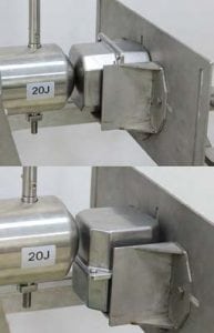
For aluminum or stainless steel cases:
A first shock is produced in the middle of each of the faces of the devices. It is then followed by 4 other shocks evenly distributed over the rest of the tested face.
The test is considered inconclusive when the largest deformation measured on the metal at any location of the different impacts is greater than 2mm Indeed, although this value is not specified in the standard, we considered that this permanent deformation would not allow the mounting of accessories.
For accessories:
When the cases are equipped with instruments, it is often the accessory which will be the most fragile part and will determine the classification. If the case is equipped with accessories (handle, indicator light, cover, switch, cable gland, etc.), a test is performed in the center of this accessory and in two orthogonal directions. The glands have varying degrees of resistance because they exist in polyamide plastic and also in metal.
The test is considered successful when this accessory is not broken and retains its function.
IK mechanical impact resistance values
| IK number | Impact energy (Joules) | Equivalent drop mass and height |
| 00 | Unprotected | No test |
| 01 | 0.15 | 200 g dropped from 7.5 cm |
| 02 | 0.2 | 200 g dropped from 10 cm |
| 03 | 0.35 | 200 g dropped from 17.5 cm |
| 04 | 0.5 | 200 g dropped from 25 cm |
| 05 | 0.7 | 200 g dropped from 35 cm |
| 06 | 1 | 500 g dropped from 20 cm |
| 07 | 2 | 500 g dropped from 40 cm |
| 08 | 5 | 1.7 kg dropped from 29.5 cm |
| 09 | 10 | 5 kg dropped from 20 cm |
| 10 | 20 | 5 kg dropped from 40 cm |
Obsolete IP third number for mechanical impact resistance
| IP third digit | Impact energy (Joules) | Equivalent drop mass and height |
| 0 | Unprotected | No test |
| 1 | 0.225 | 150 g dropped from 15 cm |
| 2 | 0.375 | 250 g cropped from 15 cm |
| 3 | 0.5 | 250 g dropped from 20 cm |
| 5 | 2 | 500 g dropped from 40 cm |
| 7 | 6 | 1.5 kg dropped from 40 cm |
| 9 | 20 | 5.0 kg dropped from 40 cm |
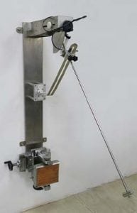
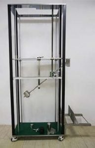
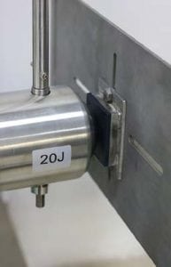
IK testing of enclosures in our laboratory
 |
 |
 |
 |
| Test equipment for IK04 to IK06 | Test equipment for IK07 to IK10 | IK 10 testing on specimen | IK10 test on enclosure |
Comparative test results of 60 x 60mm plastic specimens, 3mm thickness
| Material | PA66, 25%GF | PC | PVDF | PP |
| IK | 10 | 10 | 09 | 10 |
Comparative test results of metal specimens of 60 x 60mm, in thicknesses used on enclosures*
| 304 Stainless steel | Aluminium | |||||
| thickness | 1mm | 1.2mm | 2mm | 1.7mm | 2mm | 3mm |
| IK10 impact bump |
10.6mm | 7.5mm | 4.4mm | 11.8 | 9.7 | 0.45 |
* the value of the IK10 impact deformation of flat specimens is indicative but is not representative of the deformation of stamped or molded parts, because the shape is then predominant.
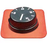
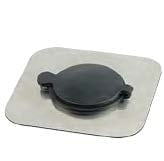
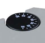
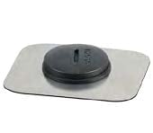
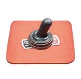
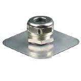
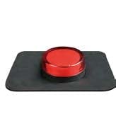
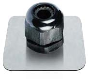
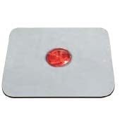
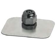
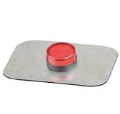
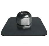
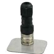
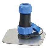
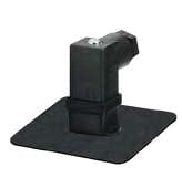
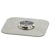
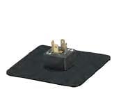
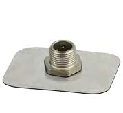
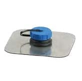
IK grade of usual accessories (For information only)
| Description | Photos | IK | Description | Photos | IK |
|
Unprotected |
 |
IK09 |
Internal access |
 |
IK10 |
|
External |
 |
IK10 |
Internal access |
 |
IK10 |
|
Unprotected |
 |
<IK04 |
M20 cable |
 |
IK10 |
|
Unprotected |
 |
IK08 |
M16 cable |
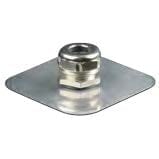 |
IK10 |
|
Dia 16mm pilot |
 |
IK10 |
M25 cable |
 |
IK10 |
|
Built in pilot |
 |
IK08 |
M16 cable |
 |
IK10 |
|
Unprotected |
 |
IK08 |
M20 cable |
 |
IK10 |
|
Miniature M12 |
 |
<IK04 |
M21 |
 |
<IK04 |
|
Dome switch |
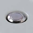 |
IK10 |
Miniature |
 |
<IK04 |
|
Toggle switch |
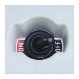 |
IK10 |
M25 cable |
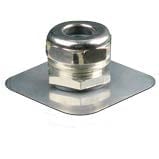 |
IK10 |
|
Unprotected |
 |
IK10 |
Miniature |
 |
<IK04 |
|
Miniature M12 |
 |
IK08 |
M21 |
 |
IK10 |
|
External |
 |
IK10 |
|
||