Operating Principle
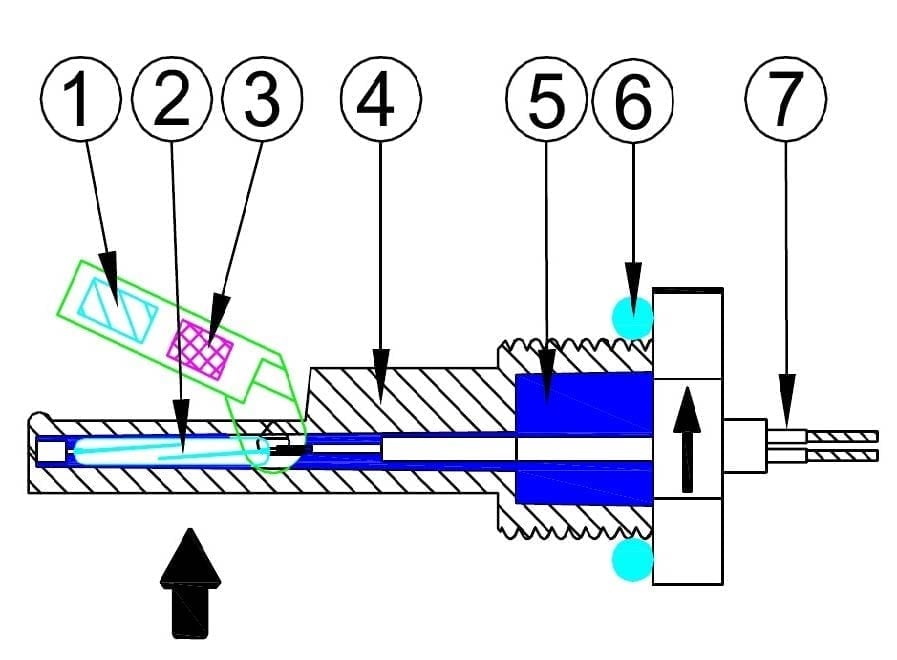
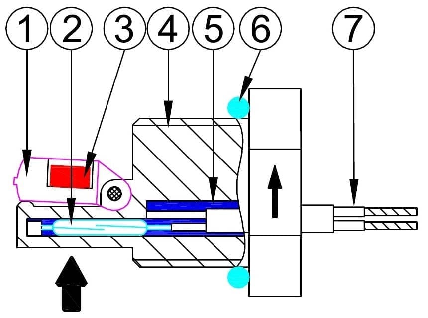
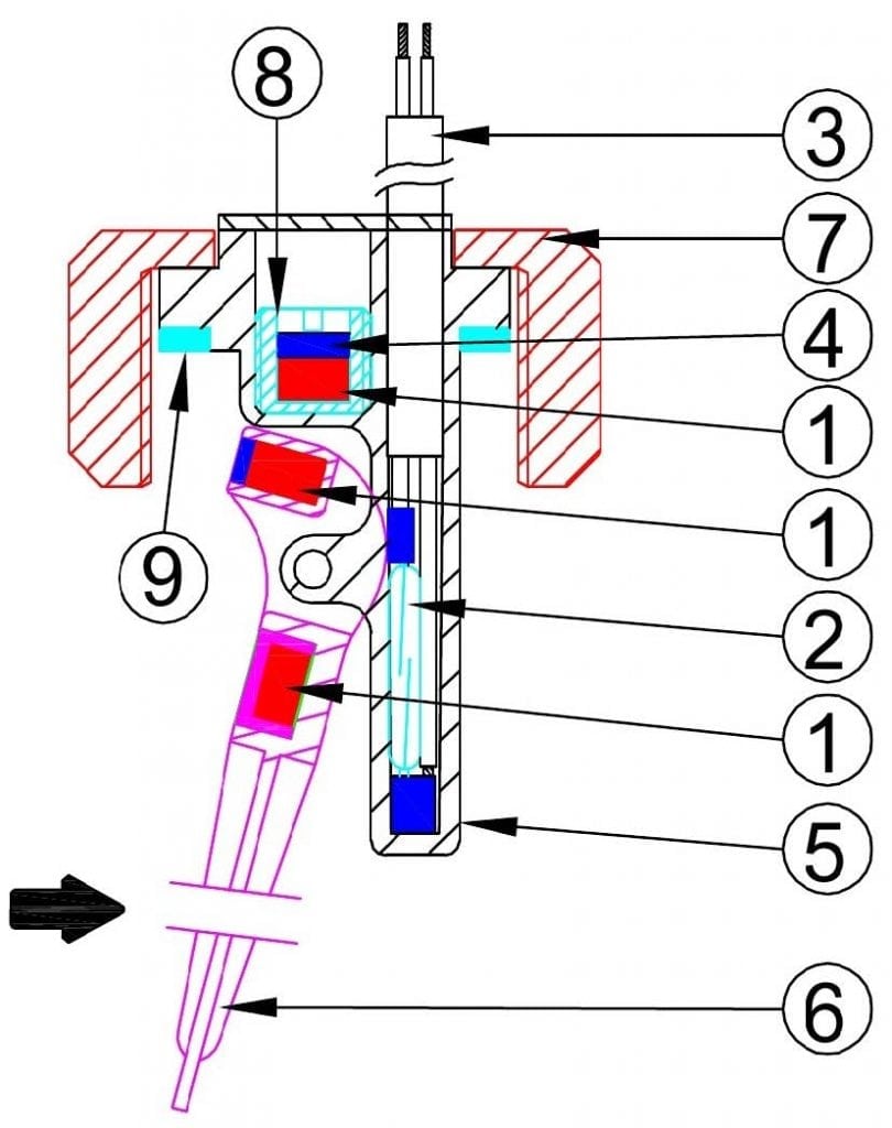
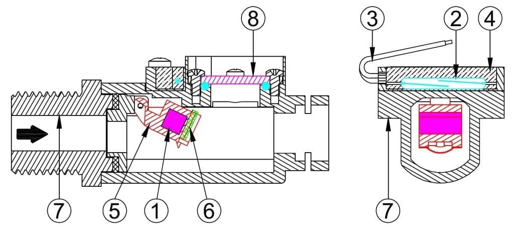
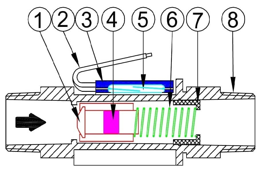
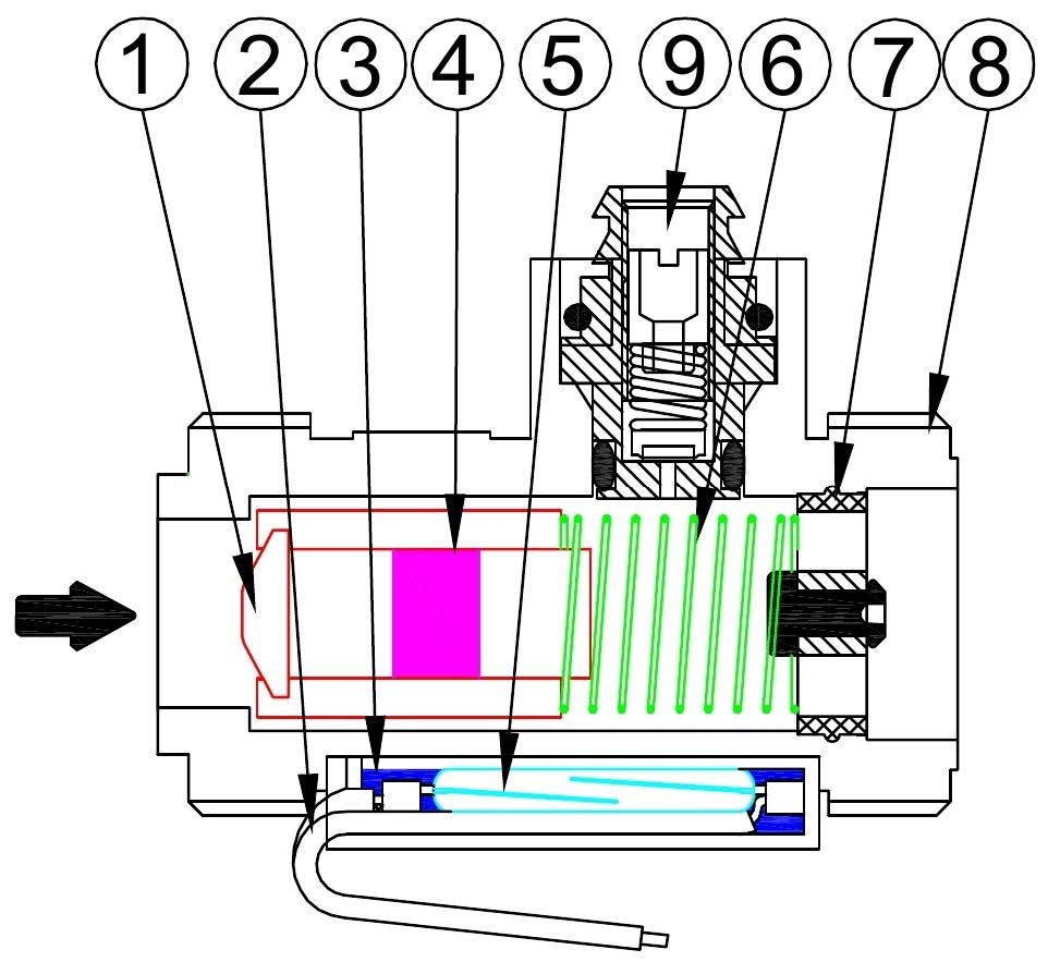
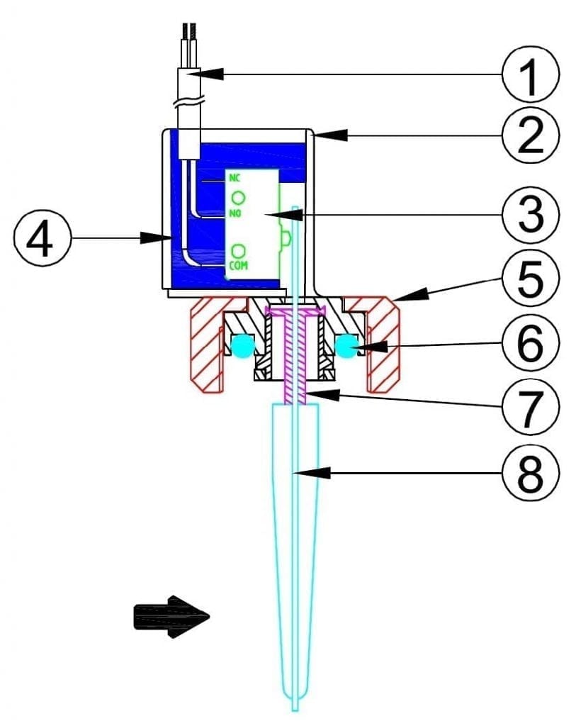
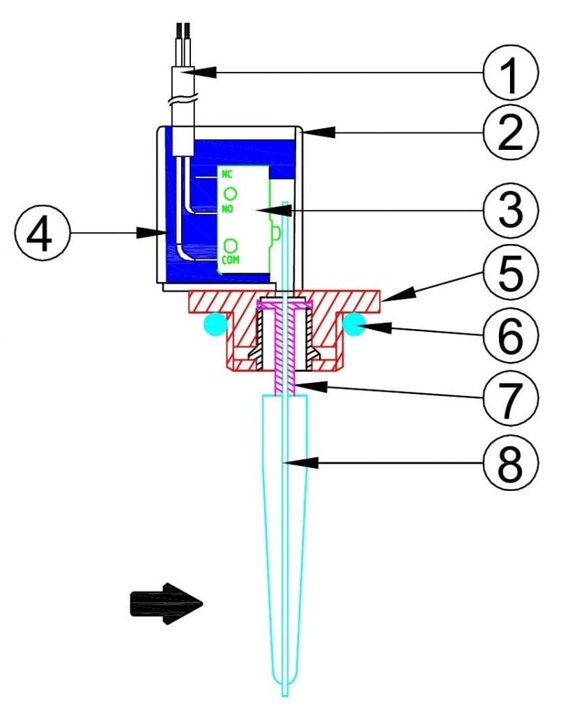
In the paddle and switch flowswitches, the paddle is pushed by the water flow and actuates a microswitch. The seal between the paddle and the electric part is made by a Santoprene elastomeric gasket. Set point calibration value is given mainly by the paddle length and its the surface, the microswitch actuating force , the pipe diameter. As in all paddle flow switches, due to the weight of the paddle, the setting will vary slightly according to the mounting position (horizontal or vertical, and in the latter case, flow inlet direction from top to bottom or from bottom to top).
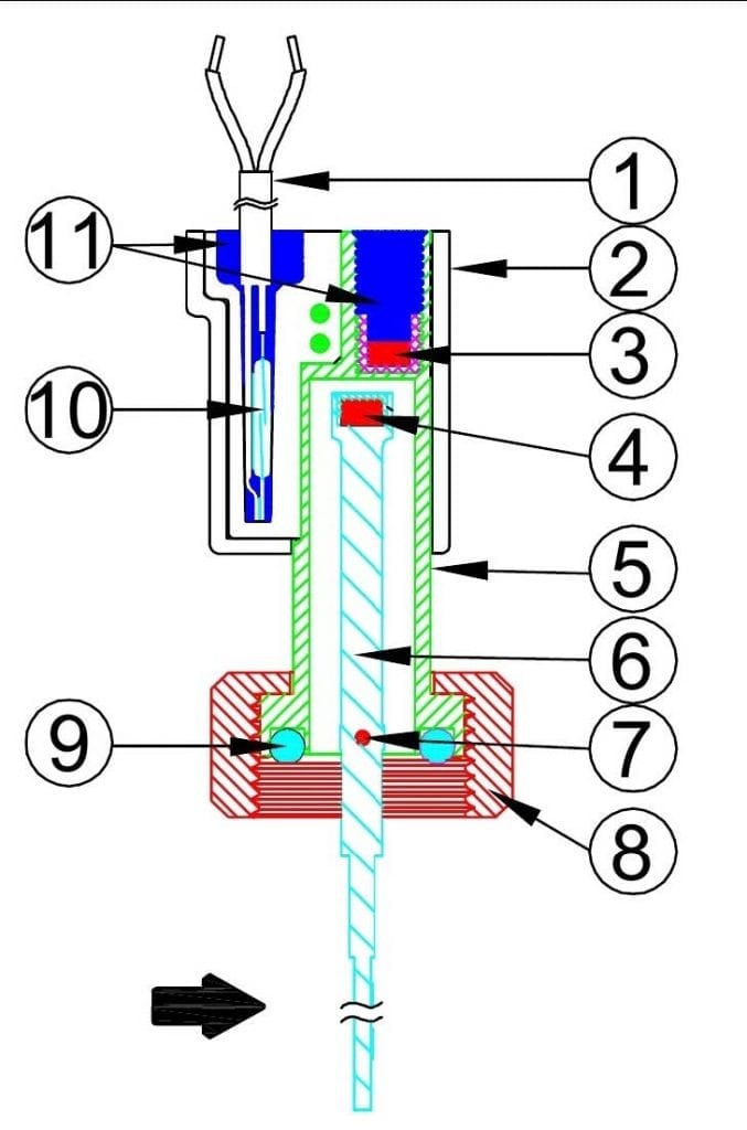
During assembly it is important to check that the paddle is correctly oriented in the flow direction and that no friction or obstacle hinders its movement. Therefore it is better to focus on devices with ¾” union nut mounting , or clips and O-ring assembly (type Ultimheat Snap-in), which allow easy aorientation djustment , unlike models with fixed thread.
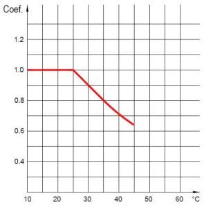
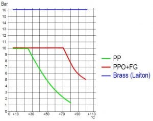
The temperature and pressure withstanding values, as well as resistance to chemical products are limited by the paddle gasket material.
These models have the advantage of high electrical rating, and do not contain magnets, allowing them for use with liquids that may contain magnetic particles.
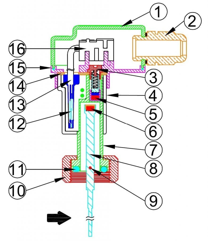
In the ½” fixed thread types, it is possible to include a built-in temperature sensor: NTC, thermocouple, or Pt100, thus allowing the liquid temperature measurement.