Explanation of printed values made on a thermostat upon IEC60-730-1 § 7-2
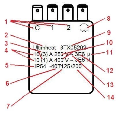
- Identification of terminals that are suitable for the connection of external conductors, and if they are suitable for line or neutral conductors, or both.
L= must be used for line in The United Kingdom, other countries no restriction. N must be used if the terminals must be used for neutral ( All countries). - Manufacturer’s name or trade mark.
- Inductive load rating with power factor = 0.6 (When inductive load value is not printed, these contacts may be used for an inductive load, provided that the power factor is not less than 0,8, and the inductive load does not exceed 60 % of the current rating provided for the resistive load.)
- Resistive load rating with power factor = 0.95+/-0.05
- Degree of protection provided by enclosure, does not apply to controls or parts thereof classified as IP00, IP10, IP20, IP30 and IP40.
- High temperature limits of the switch head (Tmax), if other than 55 °C.
- Low temperature limits of the switch head, if lower than 0 °C.
- Ground terminal identification (if existing).
- Unique type reference.
- Rated voltage or rated voltage range in volts (V) (Frequency printing is mandatory if other than for range 50 Hz to 60 Hz inclusive).
- Micro-disconnection (reduced contact gap) Printing is not mandatory.
- Number of cycles of actuation for each manual action (For manual reset thermostat).
Number of automatic cycles for each automatic action (for control thermostat). Printing is not mandatory. - For use on alternative circuit, 50 to 60Hz inclusive.
- Temperature limits of mounting surfaces (Ts) if more than 20 K above Tmax.