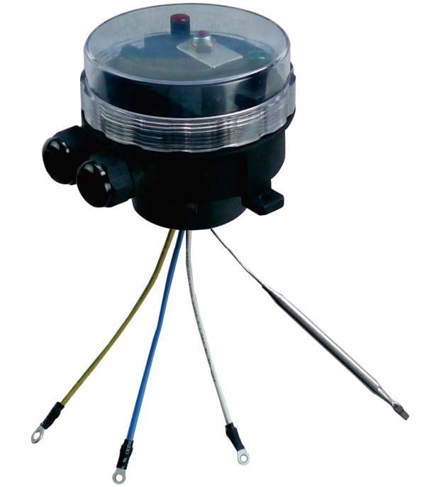
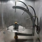
Electric fire detection switches with thermal glass bulb for air duct
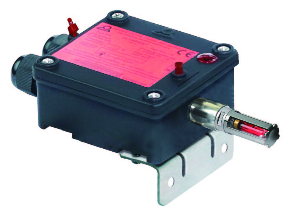
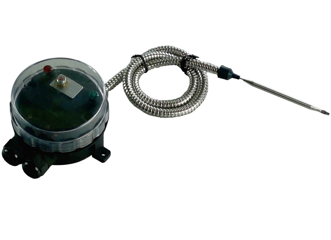
Fire detection in air ducts. This device operates electrical contacts for remote alarm and simultaneous control of electrical servo-controls such as electric cylinders, electric motors or solenoids, for opening or closing air conditioning dampers.
Applications
Fire detection in air ducts. This device operates electrical contacts for remote alarm and simultaneous control of electrical servo-controls such as electric cylinders, electric motors or solenoids, for opening or closing air conditioning dampers.
Main Features
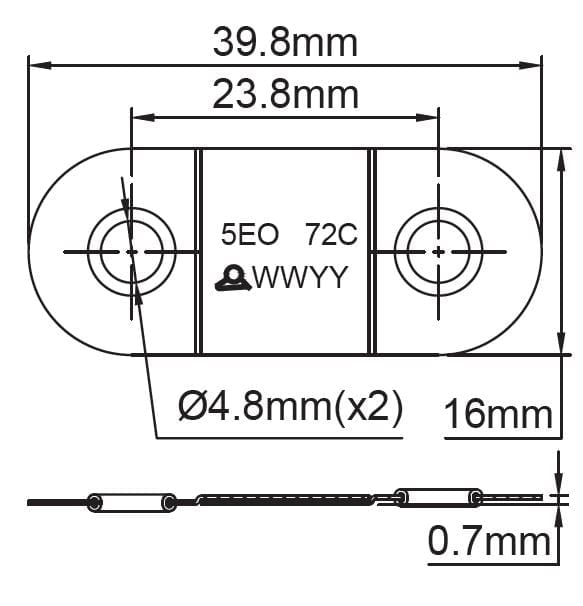
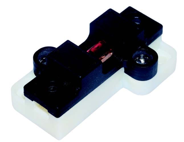
Thermal sensitive part: Thermo-breakable bulb Operation: The break of the bulb activates, by means of a pusher, an electric switch.
Mounting: Enclosure with stainless steel bracket for mounting on air duct wall, with sensing element located
inside the air flow.
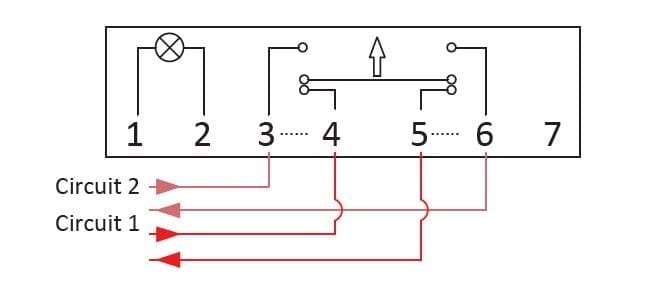
Electrical contact: Double snap action contact with two independent circuits, one normally open and the other normally closed. Total contact spacing is larger than 3mm, providing full disconnection upon IEC standards.
Electrical rating: 16A (4A) 250VAC; 10A (1A) 400VAC; 4A (100mA) 24 and 48VDC. Compatible with electric door magnets in 24V and 48V, 500 N.
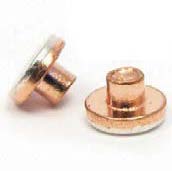
(Version with gold plated contacts for low level electronic circuits available on request).
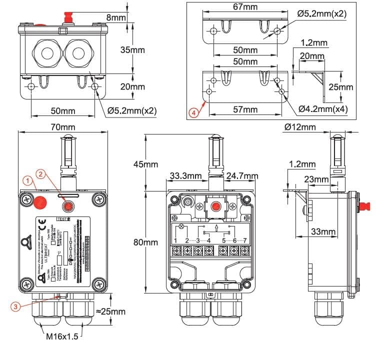
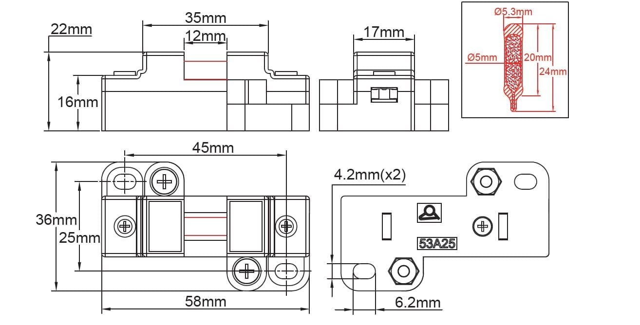
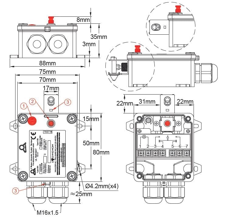
Enclosure: 70 x 80 x 40mm in UV resistant black PA66, with captive lid screws in stainless steel.
- Flammability: UL94V0 and GWFI 960°C.
- Deformation temperature under load: 225°C. (ISO 75-2, 1.8 MPa).
- Ambient temperature class T150°C.
- Resistance to corrosion better than 1000 hours in salt spray fog at 5%.
- Ingress resistance: The highest class, IP69K (washable at high pressure hot water cleaner).
- Impact resistance: The highest class, IK10 (except stainless steel support for temperature-sensitive parts and glass bulbs).
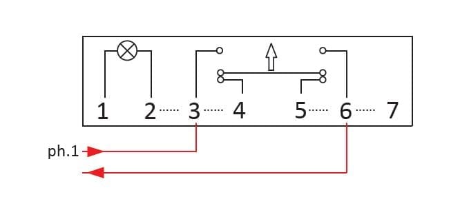
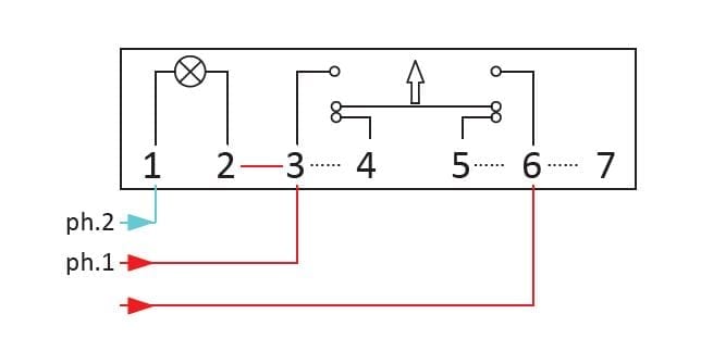
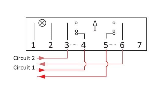
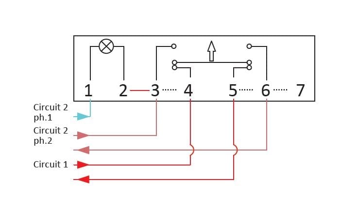
Electrical connection: On screw terminal block, 7 terminals 2.5mm². Shipped with a 3-way shunt and a 2-way shunt, allowing different contact and connection arrangement solutions. Cable outlet by two M16 cable glands.
Maintenance:
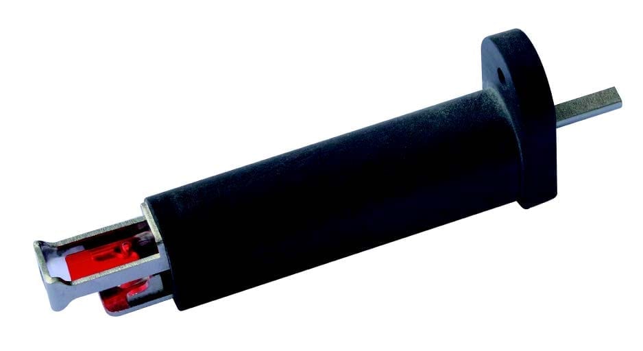
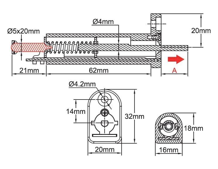
- Easy replacement of the temperature-sensitive
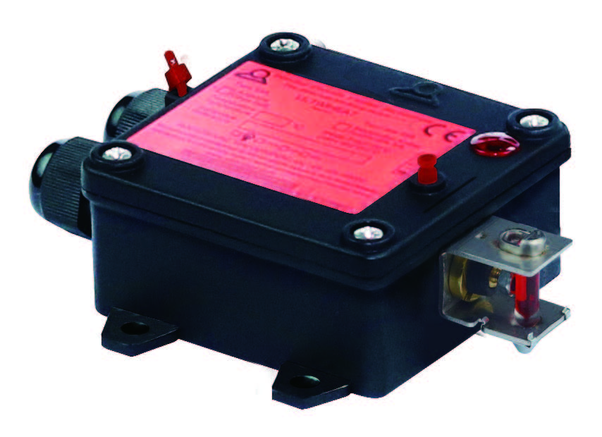
- A test button (option) accessible from the outside allows to check instantly the operation of the switch without any disassembly or opening.
- The enclosure has holes for the installation of seals preventing unauthorized opening.
Visualization: Optional 230 V, 24V or 48V pilot light. This pilot light can be used to visualize the presence of voltage on the line, a critical parameter for “contact closes on fire” detection systems.
Other options: Customization and customer labelling. Output by a single cable gland.
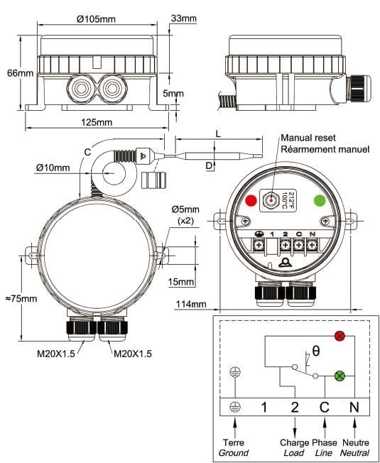
Wiring diagrams
Main references
Main references ( type 59A8 )
|
Operating temperature |
Reference without test button, without pilot light | Reference without test button, with 230V pilot light* | Reference with test button, without pilot light | Reference with test button and 230V pilot light** |
| Without thermal bulb | 59A80PS1630003C | 59A81PS1630003C | 59A8AP2S1630003C | 59A8BP2S1630003C |
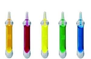
| 57°C (135°F), orange color bulb | 59A80PS1630573C | 59A81PS1630573C | 59A8AP2S1630573C | 59A8BP2S1630573C |
| 68°C (155°F)red color bulb | 59A80PS1630683C | 59A81PS1630683C | 59A8AP2S1630683C | 59A8BP2S1630683C |
| 79°C (174°F) yellow color bulb | 59A80PS1630793C | 59A81PS1630793C | 59A8AP2S1630793C | 59A8BP2S1630793C |
| 93°C (199°F) green color bulb | 59A80PS1630933C | 59A81PS1630933C | 59A8AP2S1630933C | 59A8BP2S1630963C |
| 141°C (286°F) blue color bulb | 59A80PS1631413C | 59A81PS1631413C | 59A8AP2S1631413C | 59A8BP2S1631413C |
* – For models without test button with 24V pilot light, replace 1P by 2P in the reference
– For models without test button with 48V pilot light, replace 1P by 3P in the reference
** – For models with test button with 24V pilot light, replace BP by CP in the reference
– For models with test button with 48V pilot light, replace BP by DP in the reference
Spare parts references*
| Thermal glass bulbs for 59A7 (Packing units 50 and 250p) | ||||||
 |
57°C (135°F) |
6658GBB057 |
||||
| 68°C (155°F) |
6658GBB068 |
|||||
|
79°C (174°F) |
6658GBB079 |
|||||
|
93°C (199°F) |
6658GBB093 |
|||||
| 141°C (286°F) |
6658GBB141 |
|||||
* Maintenance or replacement of thermal bulbs or fusible links must be made by specially trained personnel and in accordance with our technical instructions.
Downloads
Datasheets
Drawings
Related products
Immersion heater temperature limiter boxes
Rod temperature limiter boxes
Remote temperature limiter boxes
Immersion heater temperature control boxes
Technical informations associated to this product
-
Historical and technical introduction of fusible alloys and fire safety fusible links
The earliest known piece made of lead and tin alloy seems to be an Egyptian vase found in Abydos, dated around 1400 BC. During the Roman Empire, lead was used for the construction of water pipes. Melting at 325°C, -
Temperature sensing principles
The bimetal strip is formed by two co-laminated metal. One has a high coefficient of expansion, the othera lower or zero. When the strip is heated, it bends proportionally to the temperature. These bimetal blades are generally flat and fixed at one end. But they can be wound in a spiral shape, although this arrangement most often used in the construction of thermometers. -
Electrical contacts
As numerous mechanisms exist, we decided not to distinguish on the basis of constructive technique, but according to their operation speed, which is the key element. -
Electrical protection classes
The housings are designed to protect electrical equipment located inside. This protection must be considered in the electrical and environmental angles.)

