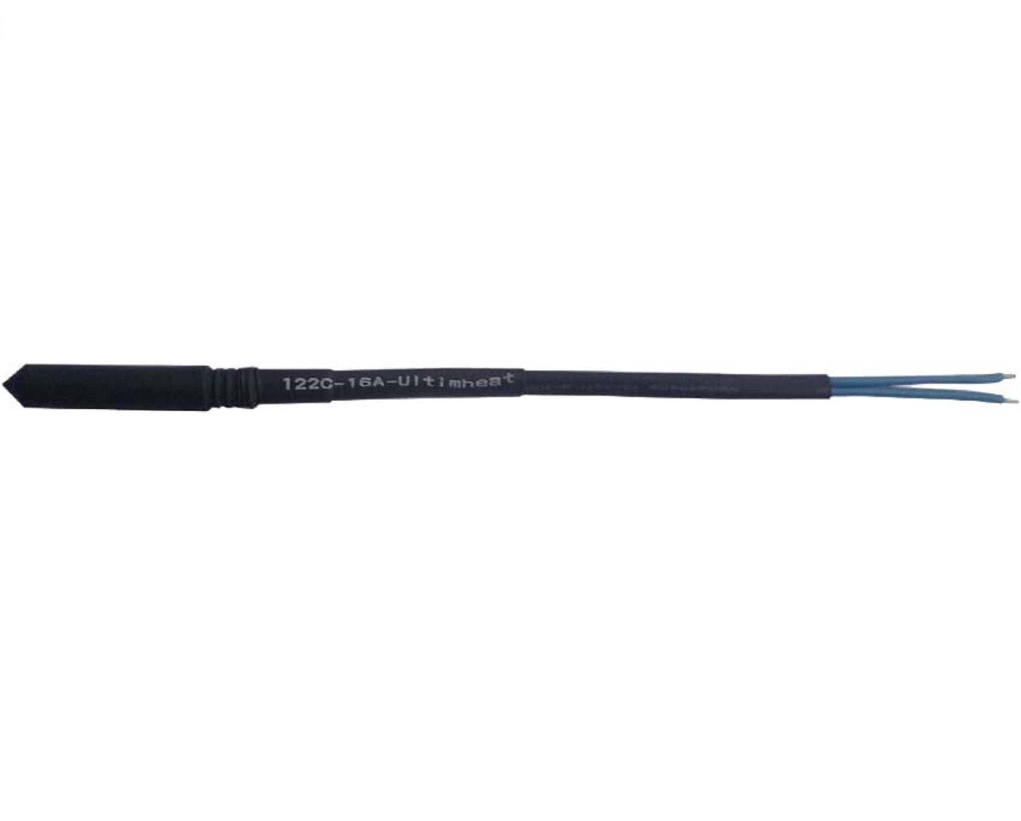
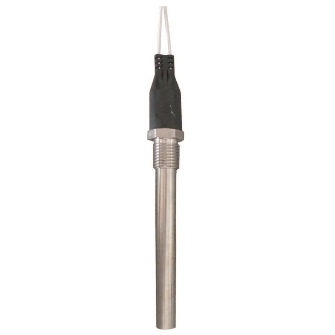
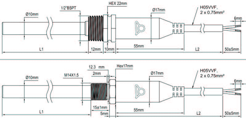
Wired thermal fuses, for insertion into 8.5 mm I.D. pockets
Protection against overheating of equipment and heating elements
| Electrical rating | |
|---|---|
| Voltage | |
| Rated functioning temperature (°C) Tf | 73, 79, 85, 94, 99, 108, 113, 122, 133, 142, 157, 167, 172, 184, 192, 216, 227, 240 |
| Holding temperature (°C) Th | 101, 114, 127, 130, 145, 156, 164, 189, 190, 45, 52, 57, 66, 71, 77, 84, 94 |
| Maximum temperature (°C) Tm |
TECHNICAL FEATURES
Applications: protection against overheating of equipment and heating elements
Fusible pellet: organic compound
Mechanism: movable pellet actuated of a spring released by the fusion of the pellet
Protection: with electrical insulation silicone boot, dia. 8mm
Nominal current rating: 16A 250V
The nominal current rating is the maximum current the fuse can carry without opening or deteriorate when subjected to a temperature known as the “holding temperature” (Th) for a limited time
Holding temperature (Th): the fuse must not open or be destroyed when subjected to a temperature equal to Th-6 °C for a period of 168 hours under nominal voltage and current
Rated functioning temperature (Tf): It is the opening temperature of the fuse in a calibration oven, when subjected to a current less than 10 mA, when temperature rises at a speed of 0.5 to 1 °C / min. The opening temperature must not be lower than Tf-10
°C or above Tf under these conditions. This is the operating temperature Tf which is printed on the fuse and the protective sheath external of the leads.
Maximum temperature (Tm): it is the maximum temperature withstood by the fuse after opening without losing its insulating and mechanical properties.
Insulation voltage between open contacts: ≥ 500V
Insulation resistance between open contacts: ≥ 0.2 MΩ @ 500V
Lead lengths: 500 mm.
Leads: FEP 300V primary insulation, 1 mm² gauge (AWG18), in a polyolefin sheath.
Main references
| Reference | Rated functioning temperature °C/°F (Tf) | Holding temperature °C/°F (Th) | Maximum temperature °C/°F (Tm) |
| 5MA3SPF070F18500 | 73°C/163.4°F | 45°C/113°F | 115°C/239°F |
| 5MA3SPF077F18500 | 79°C/174.2°F | 52°C/125.6°F | 125°C/257°F |
| 5MA3SPF084F18500 | 85°C/185°F | 57°C/134.6°F | 125°C/257°F |
| 5MA3SPF091F18500 | 94°C/201.2°F | 66°C/150.8°C | 140°C/284°F |
| 5MA3SPF096F18500 | 99°C/210.2°F | 71°C/159.8°F | 140°C/284°F |
| 5MA3SPF106F18500 | 108°C/226.4°F | 77°C/170.6°F | 145°C/293°F |
| 5MA3SPF109F18500 | 113°C/235.4°F | 84°C/183.2°F | 150°C/302°F |
| 5MA3SPF121F18500 | 122°C/251.6°F | 94°C/201.2°F | 175°C/347°F |
| 5MA3SPF129F18500 | 133°C/271.4°F | 101°C/213.8°F | 175°C/347°F |
| 5MA3SPF139F18500 | 142°C/287.6°F | 114°C/237.2°F | 185°C/365°F |
| 5MA3SPF152F18500 | 157°C/314.6°F | 127°C/260.6°F | 195°C/383°F |
| 5MA3SPF165F18500 | 167°C/332.6°F | 130°C/266°F | 205°C/401°F |
| 5MA3SPF169F18500 | 172°C/341.6°F | 145°C/293°F | 215°C/419°F |
| 5MA3SPF182F18500 | 184°C/363.2°F | 156°C/312.8°F | 225°C/437°F |
| 5MA3SPF188F18500 | 192°C/377.6°F | 164°C/327.2°F | 245°C/473°F |
| 5MA3SPF216F18500 | 216°C/420.8°F | 189°C/372.2°F | 280°C/536°F |
| 5MA3SPF227F18500 | 227°C/440.6°F | 190°C/374°F | 295°C/563°F |
| 5MA3SPF240F18500 | 240°C/464°F | 190°C/374°F | 305°C/581°F |
Downloads
Related products
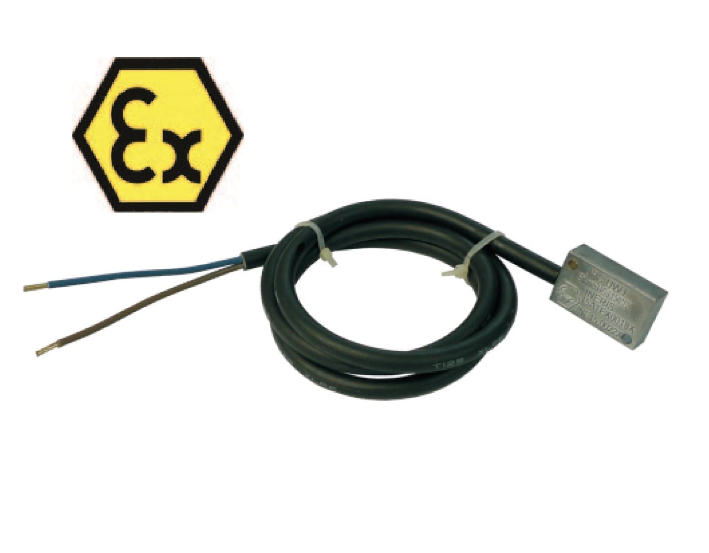
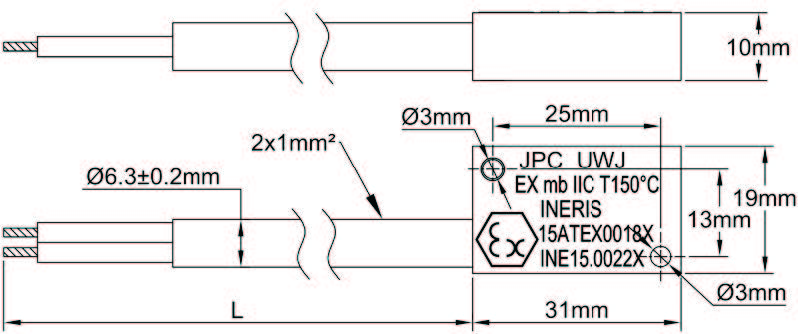
Explosion proof ATEX/IECEx temperature limiters
Thermal cut out (TCO)
Technical informations associated to this product
-
Description of temperature controls
Used as control thermostats or as a safety thermostat with manual reset, these thermostats have a disc made of two different metals laminated together for temperature sensing element. These two metals have different expansion coefficients. -
Thermostats installation
The proper functioning of a thermostat depends primarily on the correct choice of the component, but also the conditions of its installation. Conditions used to calibrate regulating and control equipment in the factory are always ideal laboratory conditions, ensuring measurement accuracy and repeatability. These conditions are rarely those found in practice when installing thermostats. However, with a minimum of constraints, it is possible to optimize assemblies. -
Electrical contacts
As numerous mechanisms exist, we decided not to distinguish on the basis of constructive technique, but according to their operation speed, which is the key element. -
Electrical protection classes
The housings are designed to protect electrical equipment located inside. This protection must be considered in the electrical and environmental angles.)

