Thermal cut outs, 10 and 16A 250V, axial wires
Overheat protection of electrical or electronic equipment, home appliances, electrical coils and heating components.
| Voltage | |
|---|---|
| Electrical rating | |
| Rated functioning temperature (°C) Tf | 73, 79, 85, 94, 99, 108, 113, 122, 133, 142, 157, 167, 172, 184, 192, 216, 227, 240 |
| Holding temperature (°C) Th | 101, 114, 127, 130, 145, 156, 164, 189, 190, 45, 52, 57, 66, 71, 77, 84, 94 |
| Maximum temperature (°C) Tm |
TECHNICAL FEATURES
Main application: Overheat protection of electrical or electronic equipment, home appliances, electrical coils and heating components.
Important notice: The proper function of this component not only depends of its rated temperature, but also of its assembly position, connection and electrical current.
Housing: Silver plated copper. This is a non-insulated electric life part. Protect from human contact and use appropriate design to avoid electrical shocks and hazards. Do not bend or make holes in housing
Ingress protection: TCO are not waterproof, do not immerse in liquid.
Insulation: 95% alumina, epoxy sealed. Do not submit epoxy sealing to temperature over 200°C
Melting pellet: Organic compound
Mechanism type: spring operated movable contact, operated by the melting pellet
Terminals: tin plated copper wires
Wiring rules:
Mechanical resistance: do not submit TCO wires to pulling force over 16N or pushing force over 4N
Bending: do not bend or cut wires at less than 6 mm from epoxy sealing or housing
Crimping: Do not submit to impact or mechanical force during terminals crimping. Wrong crimping will overheat the wire by Joule effect, fuse will melt, and epoxy seal will burn down. Parts crimped to TCO wires must with have enough mechanical strength and hardness to withstand normal vibration and impact, and it must not cause stresses due to heat dilatation
Tin welding: it is not allowed to use tin welding for fuse with rated temperature under 184°C without proper wire cooling solution to avoid fuse to melt.
Electrical welding: proper wire cooling solution must be used to avoid fuse to melt wire, and welding current cannot go through the fuse;
Shrinkable sleeves: do not use shrinkable sleeves, it will melt down the TCO during the shrinking process
Environment corrosion: TCO must be protected from corrosive environment, air or fumes.
Rated voltage: 250V(AC)
Rated current: 10A and 16A (2 different types)
The rated current is the max current that the TCO can carry without opening or change in calibration temperature, when submitted at a limited temperature named “Holding temperature” (Th), during a limited time.
Rated temperature (Tf): it is the fuse contact opening temperature measured inside calibration oven, with a current lower than 10 mA and a temperature rise of 0.5 to1°C/min. Opening temperature cannot be below Tf -10°C and not higher than Tf. It is this temperature that is printed on the TCO.
Holding temperature (TC): TCO must not open or be destroyed when submitted during 168 hours at Th-6°C, at nominal voltage and rating
Max ultimate temperature(Tm): It is the maximum temperature that the fuse can withstand, after opening, without change in its mechanical and insulation properties
Electrical strength between contacts after opening: ≥500V
Insulation resistance between contacts after opening: ≥ 0.2MΩ under 500V.
Joule effect temperature increase: lower than 15°C measured at the center of the fuse under nominal load.
Standard: DIN EN60691(VDE 0821):2007-09 EN60691:2003+A1: 2007.IEC60691(ed.3);am1
Product identification:
SPF169: model number
TF172C: rated operation temperature
(Tf) 10A250V: rated current and voltage
088: production number
Installation and safety instructions:
- Choose TCO temperature fuse which electrical insulation will not be effected by equipment
- TCO replacement must be made by exactly the same model of the same supplier
Main references
| Reference with 10A rating | Reference with 16A rating | Rated functioning temperature °C/°F (Tf) | Holding temperature °C/°F (Th) | Maximum temperature °C/°F (Tm) |
| 5MA3SPF070019340 | 5MA3SPF070H19340 | 73°C/163.4°F | 45°C/113°F | 115°C/239°F |
| 5MA3SPF077019340 | 5MA3SPF077H19340 | 79°C/174.2°F | 52°C/125.6°F | 125°C/257°F |
| 5MA3SPF084019340 | 5MA3SPF084H19340 | 85°C/185°F | 57°C/134.6°F | 125°C/257°F |
| 5MA3SPF091019340 | 5MA3SPF091H19340 | 94°C/201.2°F | 66°C/150.8°C | 140°C/284°F |
| 5MA3SPF096019340 | 5MA3SPF096H19340 | 99°C/210.2°F | 71°C/159.8°F | 140°C/284°F |
| 5MA3SPF106019340 | 5MA3SPF106H19340 | 108°C/226.4°F | 77°C/170.6°F | 145°C/293°F |
| 5MA3SPF109019340 | 5MA3SPF109H19340 | 113°C/235.4°F | 84°C/183.2°F | 150°C/302°F |
| 5MA3SPF121019340 | 5MA3SPF121H19340 | 122°C/251.6°F | 94°C/201.2°F | 175°C/347°F |
| 5MA3SPF129019340 | 5MA3SPF129H19340 | 133°C/271.4°F | 101°C/213.8°F | 175°C/347°F |
| 5MA3SPF139019340 | 5MA3SPF139H19340 | 142°C/287.6°F | 114°C/237.2°F | 185°C/365°F |
| 5MA3SPF152019340 | 5MA3SPF152H19340 | 157°C/314.6°F | 127°C/260.6°F | 195°C/383°F |
| 5MA3SPF165019340 | 5MA3SPF165H19340 | 167°C/332.6°F | 130°C/266°F | 205°C/401°F |
| 5MA3SPF169019340 | 5MA3SPF169H19340 | 172°C/341.6°F | 145°C/293°F | 215°C/419°F |
| 5MA3SPF182019340 | 5MA3SPF182H19340 | 184°C/363.2°F | 156°C/312.8°F | 225°C/437°F |
| 5MA3SPF188019340 | 5MA3SPF188H19340 | 192°C/377.6°F | 164°C/327.2°F | 245°C/473°F |
| 5MA3SPF216019340 | 5MA3SPF216H19340 | 216°C/420.8°F | 189°C/372.2°F | 280°C/536°F |
| 5MA3SPF227019340 | 5MA3SPF227H19340 | 227°C/440.6°F | 190°C/374°F | 295°C/563°F |
| 5MA3SPF240019340 | 5MA3SPF240H19340 | 240°C/464°F | 190°C/374°F | 305°C/581°F |
Downloads
Related products
Disc temperature limiters
Bimetal surface thermostats
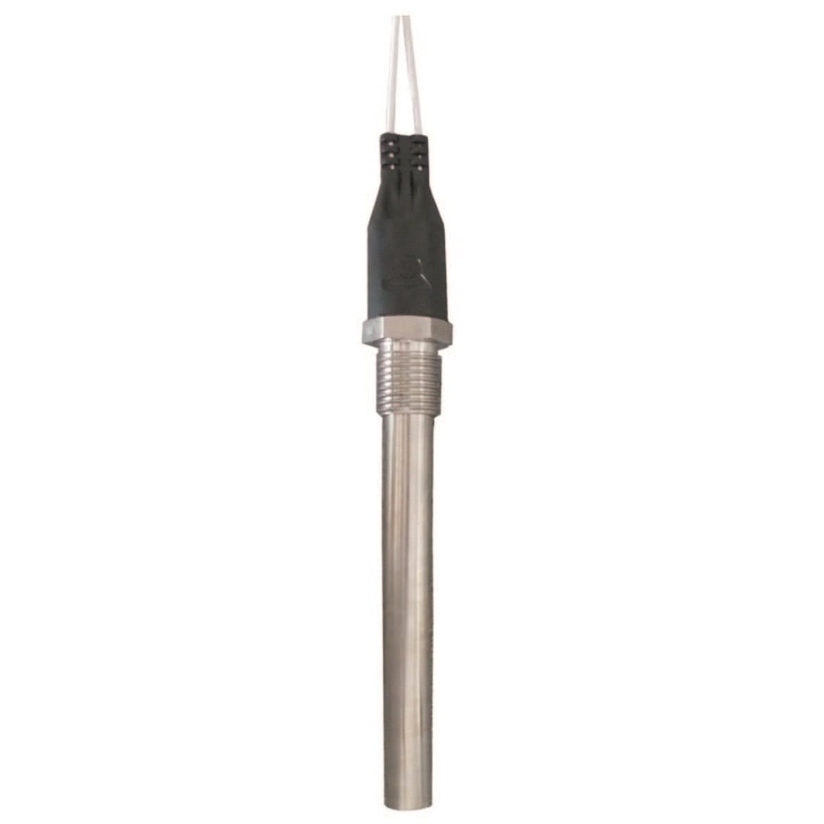
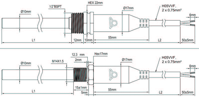
Dia. 10mm cartridge thermostat 1/2″BSPT or M14x1.5 fitting, calibration from 50 to 120°C
Technical informations associated to this product
-
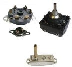
Description of temperature controls
Used as control thermostats or as a safety thermostat with manual reset, these thermostats have a disc made of two different metals laminated together for temperature sensing element. These two metals have different expansion coefficients. -
Thermostats installation
The proper functioning of a thermostat depends primarily on the correct choice of the component, but also the conditions of its installation. Conditions used to calibrate regulating and control equipment in the factory are always ideal laboratory conditions, ensuring measurement accuracy and repeatability. These conditions are rarely those found in practice when installing thermostats. However, with a minimum of constraints, it is possible to optimize assemblies. -
Electrical protection classes
The housings are designed to protect electrical equipment located inside. This protection must be considered in the electrical and environmental angles.) -
Important extracts of standards related to control or safety circuits
§3.8.1 All-pole cut out: Cutting in two conductors in a single operation, or for three phase units, the cut of the three conductors in a single step … Note: for three-phase, the neutral lead is not considered as a power conductor.


