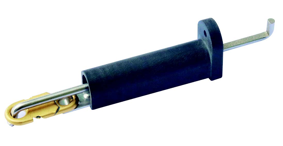
Thermal actuators with pushing action, for fire dampers, operated by eutectic fusible link
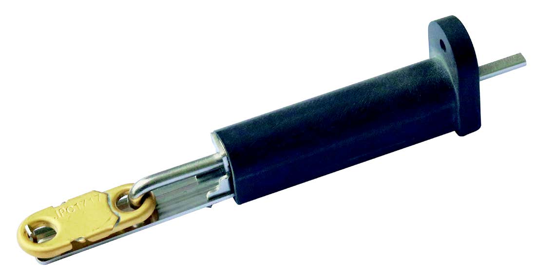
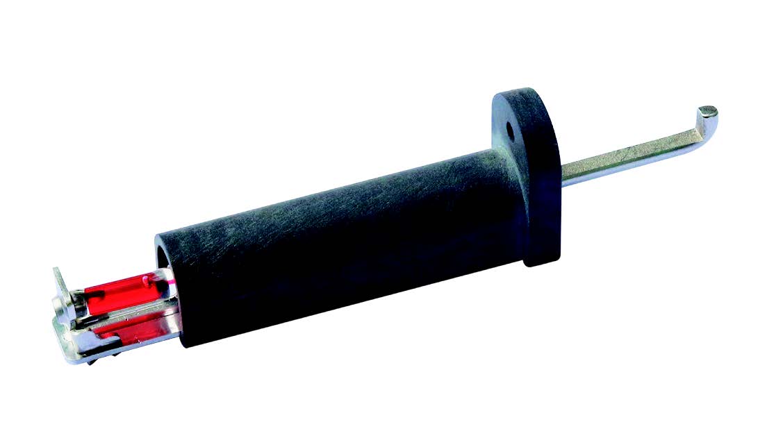
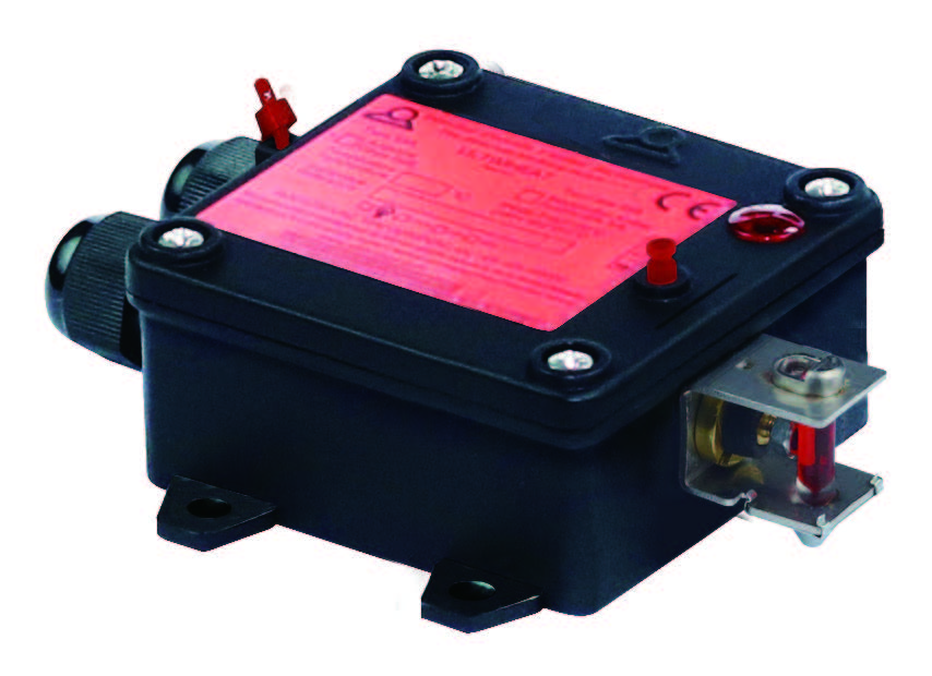
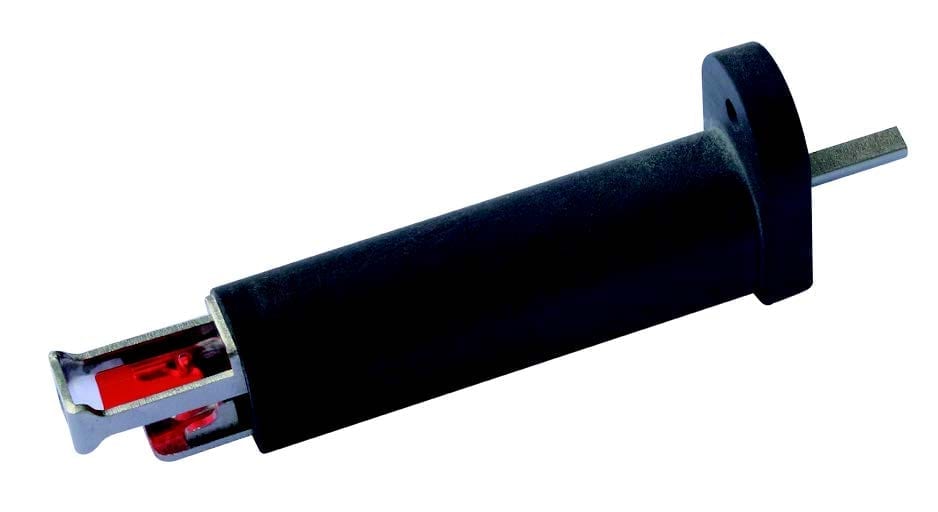
These mechanical thermal actuators are intended to close the fire dampers used on the ventilation ducts. Their large operating force unlocks the spring actuating the damper. Requiring no power supply, these devices are particularly simple and reliable. They are mandatory for all fire dampers to meet the NF-S 61.937 standard.
| Raw material | |
|---|---|
| Tripping force (DaN) | |
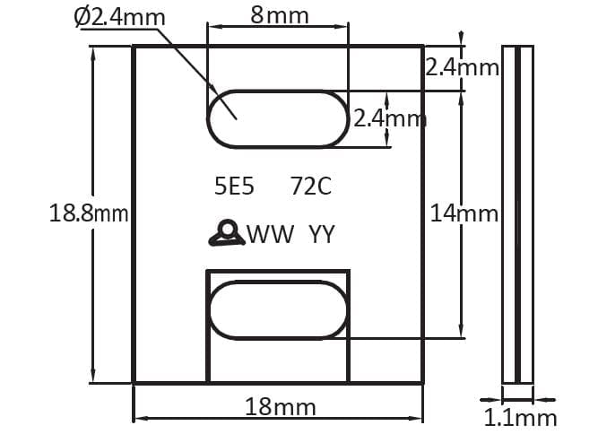
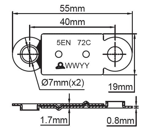
| Fusible link hole distances (mm) |
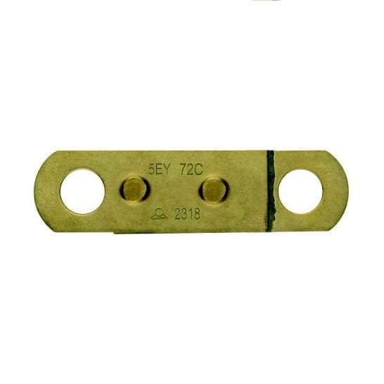
These mechanical thermal actuators are intended to close the fire dampers used on the ventilation ducts. Their large operating force unlocks the spring actuating the damper. Requiring no power supply, these devices are particularly simple and reliable. They are mandatory for all fire dampers to meet the NF-S 61.937 standard. The force they develop is compatible with eutectic alloy fusible links with a soldering surface equal to or greater than 200mm² *. However, some local regulations may require periodic replacement of the fuse link or the thermal actuator.
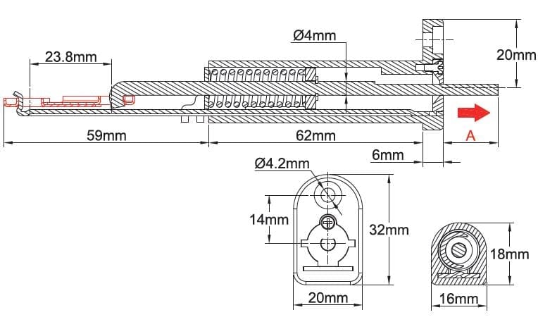
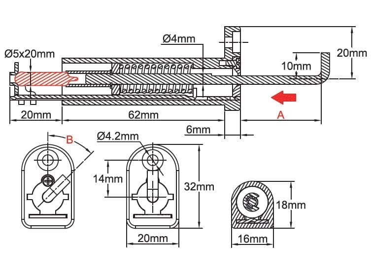
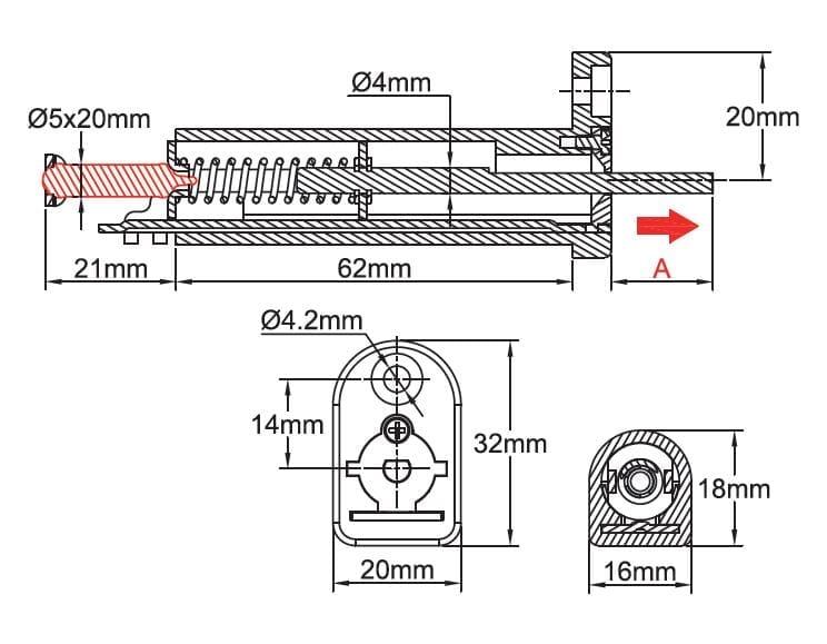
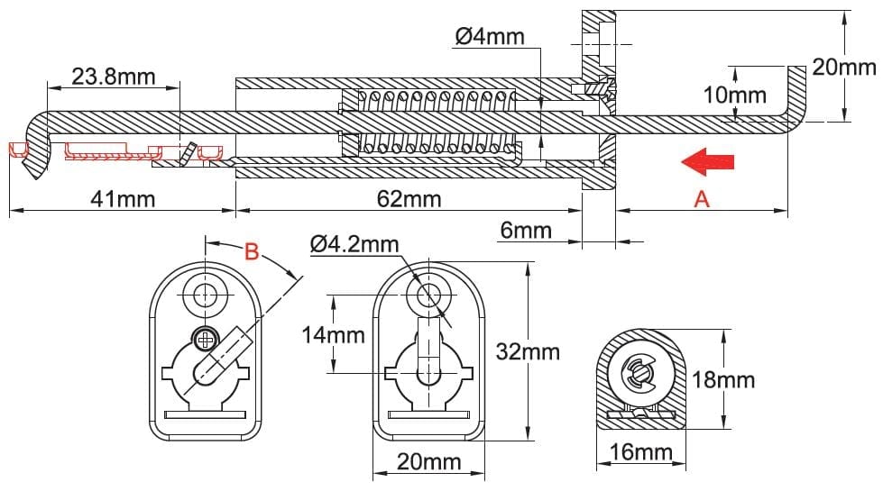
Length (A) of the actuating rod before release: 5, 10 or 15mm
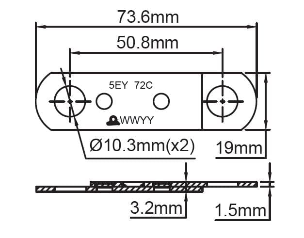
(This length is given for a type 5EE fusible link with 23.8mm between holes axis, and varies proportionally to the fusible link holes axis distance).
Stroke of the actuating rod when triggering: ≥ 20 mm
Pushing force of the actuating rod: ≥ 15 DaN (at the beginning of the stroke).
Communication with the external environment: The mechanisms are equipped with a low leakage wall, separating the air of the ventilation duct from that of the external environment.
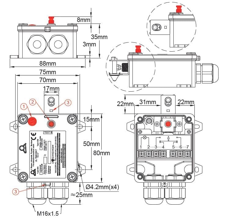
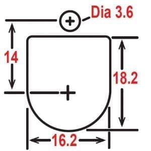
Installation: Through the wall of the ventilation duct, with M4 screws or self-tapping screws of similar dimensions. See the metal sheet cutting drawing below.
| Mounting hole dimensions (mm) |
 |
Body material: PA66 glass fiber reinforced, withstand temperature 200 °C
Mechanism material: Stainless steel Aisi 304
ROHS compliance: These mechanisms are ROHS compliant, but the conformity of the assembly when fitted with fusible links depends on the conformity of the fusible link (See the technical data sheets of the fusible links).
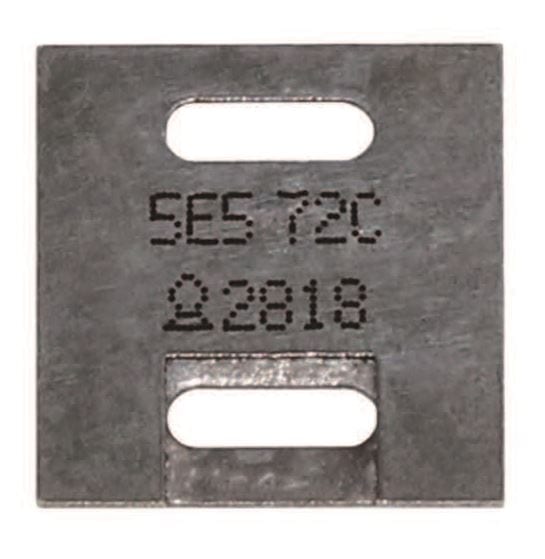
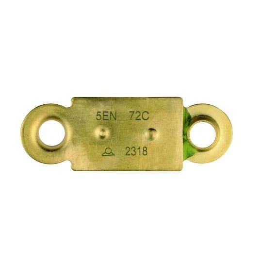
Identification: Model and date of manufacture are stamped on each mechanism. When equipped with a fusible link, the link has its own identification (See the technical data sheets of the fusible links).
Salt spray resistance: According to ISO 9227-2012, subjected to a mist formed of 20% by weight of sodium chloride in distilled water, at 35°C for 5 days (120h), the mechanisms retain their aptitude for the function.
* The permanent mechanical strength of a eutectic fusible link depends on the soldering surface, but also on the composition of the alloy and the ambient temperature. See the limiting coefficients given in the technical introduction.
Main references
Main references with 5EE fusible link (Non-ROHS)
| Temperature | Length A | Reference | Length A | Reference | Length A | Reference |
| Without fusible link | 5mm | 52B20062150B0000 | 10mm | 52B20062150C0000 | 15mm | 52B20062150C0000 |
| 68°C (155°F) | 5mm | 52B2006215EA0680 | 10mm | 52B2006215EB0680 | 15mm | 52B2006215EC0680 |
| 72°C (162°F) * | 5mm | 52B2006215EA0720 | 10mm | 52B2006215EB0720 | 15mm | 52B2006215EC0720 |
| 96°C (205°F) | 5mm | 52B2006215EA0960 | 10mm | 52B2006215EB0960 | 15mm | 52B2006215EC0960 |
| 103°C (218°F) | 5mm | 52B2006215EA1030 | 10mm | 52B2006215EB1030 | 15mm | 52B2006215EC1030 |
| 120°C (248°F) | 5mm | 52B2006215EA1200 | 10mm | 52B2006215EB1200 | 15mm | 52B2006215EC1200 |
Main references with 5EE fusible link (ROHS compliant)
| Temperature | Length A | Reference | Length A | Reference | Length A | Reference |
| 60°C (140°F) | 5mm | 52B2006215RA0600 | 10mm | 52B2006215RB0600 | 15mm | 52B2006215RC0600 |
| 72°C (162°F) * | 5mm | 52B2006215RA0720 | 10mm | 52B2006215RB0720 | 15mm | 52B2006215RC0720 |
| 79°C (174°F) | 5mm | 52B2006215RA0790 | 10mm | 52B2006215RB0790 | 15mm | 52B2006215RC0790 |
| 109°C (228°F) | 5mm | 52B2006215RA1090 | 10mm | 52B2006215RB1090 | 15mm | 52B2006215RC1090 |
| 117°C (242°F) | 5mm | 52B2006215RA1170 | 10mm | 52B2006215RB1170 | 15mm | 52B2006215RC1170 |
| 120°C (248°F) | 5mm | 52B2006215EA1200 | 10mm | 52B2006215EB1200 | 15mm | 52B2006215EC1200 |
* : tripping value often described by mistake as 70°C (158°F)
Downloads
Datasheets
Drawings
Related products
FIRE DETECTION
Technical informations associated to this product
-
Historical and technical introduction of fusible alloys and fire safety fusible links
The earliest known piece made of lead and tin alloy seems to be an Egyptian vase found in Abydos, dated around 1400 BC. During the Roman Empire, lead was used for the construction of water pipes. Melting at 325°C, -
Historical introduction to temperature measurement
The temperature measurement was preceded by a long period, throughout the 18th century, when first empirically and then gradually more accurately, have been developed measurement scales, were discovered fixed points for the calibration of these scales, and all physical variations related to temperature change: thermal expansion of gases, liquids, metals and other solids, liquefaction temperatures, boiling temperature, magnetism, thermoelectricity, just to give a few. -
Temperature sensing principles
The bimetal strip is formed by two co-laminated metal. One has a high coefficient of expansion, the othera lower or zero. When the strip is heated, it bends proportionally to the temperature. These bimetal blades are generally flat and fixed at one end. But they can be wound in a spiral shape, although this arrangement most often used in the construction of thermometers.

